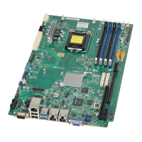
58
X11SSW-TF/-4TF User Manual
SAN MAC
+
IPMI CODE
BIOS
LICENSE
BAR CODE
MAC CODE
DESIGNED IN USA
X11SSW-TF
REV:1.01
JPW2
JSTBY1
JSD2 JSD1
JIPMB1
I-SGPIO1
I-SGPIO2
JSXB1C
JSXB1A
JSXB1B
JD1
JBAT1
SP1
JF2
JF1
JUIDB1
LED1
LED3
JL1
JPW1
JPI2C1
I-SATA5
I-SATA0
I-SATA1
I-SATA4
I-SATA3
I-SATA2
JTPM1
JBR1
JWD1
JLED1
JPME2
JPL2
JPL1
JI2C2
JI2C1
JPB1
JPG1
JBT1
DIMMA1
DIMMA2
DIMMB1
DIMMB2
BMC
PCH
JNVME1
LED2
FAN6
FAN5
VGA
FAN4 FAN3
LAN1/2
USB6/7
(3.0)
USB0/1
IPMI_LAN
COM1
FAN2
FAN1
USB9/10(3.0)
USB8(3.0)
USB4/5
USB2/3
COM2
CPU
LAN3/4
LAN1/2
CTRL
LAN3/4
CTRL
J3
1
2
CMOS Clear
JBT1 is used to clear the CMOS. Instead of pins, this jumper consists of contact pads to
prevent accidental clearing of the CMOS. To clear the CMOS, use a metal object such as a
small screwdriver to touch both pads at the same time to short the connection.
Note: Be sure to completely shut down the system, and then short JBT1 to clear the
CMOS.
SMBus to PCI Slots
Use jumpers JI
2
C1 and JI
2
C2 to connect the System Management Bus (I
2
C) to PCI-Express
slots to improve PCI performance. These two jumpers should be set at the same time. See
the table below for jumper settings. The default setting is Enabled.
I
2
C for PCI-E Slots
Jumper Settings
Jumper Setting Denition
Pins 1-2 Enabled
Pins 2-3 Disabled
1. CMOS Clear
2. SMBus to PCI Slots

 Loading...
