EasyManua.ls Logo

Supermicro X12DPL-i6 - User Manual

Supermicro X12DPL-i6
137 pages
Print Icon
To Next Page IconTo Next Page
Loading...
USER'S MANUAL
Revision 1.0
X12DPL-i6(NT6)
Question and Answer IconNeed help?

Do you have a question about the Supermicro X12DPL-i6 and is the answer not in the manual?

Overview

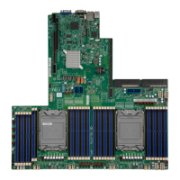
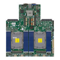
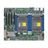
The Supermicro X12DPL-i6(NT6) is a high-performance motherboard designed for enterprise applications, big data, and high-end computing platforms. It supports dual 3rd Generation Intel® Xeon® Scalable Processors (in Socket P+ LGA 4189) with a Thermal Design Power (TDP) of up to 185W. The motherboard is built with the Intel C621A chipset, offering advanced data protection capabilities, including Trusted Platform Module (TPM) and Root of Trust (RoT) support.

Technical Specifications:

  • Processors: Supports two 3rd Gen. Intel Xeon Scalable Processors (Socket P+ LGA 4189) with a TDP of up to 185W. Performance improvements include higher core counts and up to two UPIs between sockets at 10.4GT/s. It also supports Vector Neural Network Instructions (VNNI) for accelerated training and new hardware-enhanced security features for platform and data protection without compromising performance. High PCIe performance (PCIe 4.0) with double the bandwidth of PCIe 3.0 is also a key feature.
  • Chipset: Intel PCH C621A.
  • Memory: Eight 288-pin DIMM slots supporting up to 2TB of 3DS LRDIMM/LRDIMM/3DS RDIMM/RDIMM DDR4 ECC memory. Supported memory speeds are 3200/2933/2666MHz. DIMM sizes up to 256GB at 1.2V are supported. Memory speed and capacity support are dependent on the processors used.
  • Expansion Slots: Four PCIe 4.0 x16 slots (CPU2 SLOT1 / CPU1 SLOT2 / CPU1 SLOT3 / CPU1 SLOT4). Two PCIe 4.0 x4 M.2 slots (supporting M-key 2280 and 22110 form factors). One PCIe 4.0 x8 SlimSAS port with support for two NVMe connections (X12DPL-NT6 only).
  • Networking:
    • X12DPL-i6: Two 1G Ethernet LAN ports supported by Intel i210 LAN controller.
    • X12DPL-NT6: Two 10G Ethernet LAN ports supported by Intel X550 LAN controller.
    • One dedicated BMC LAN port on the rear I/O panel (via AST2600 BMC). All LAN ports accept RJ45 cables.
  • Baseboard Management Controller (BMC): ASPEED AST2600 BMC.
  • Graphics: Graphics controller and VGA support via ASPEED AST2600 BMC.
  • I/O Devices:
    • Serial (COM) Port: One front-accessible serial port header (COM2).
    • SATA 3.0: Eight Intel PCH SATA 3.0 ports at 6GB/s (I-SATA0-7) with RAID 0, 1, 5, 10 support. I-SATA0/1 are Intel PCH Powered I-SATA 3.0 ports with SuperDOM (Disk on Module) support. Four Intel PCH SATA 3.0 ports at 6GB/s (S-SATA0-3) with RAID 0, 1, 5, 10 support.
    • Video (VGA) Connection: One VGA port on the rear I/O panel.
    • USB: Two USB 3.0 ports on the rear I/O panel (USB0, USB1). One internal USB 3.0 Type-A header (USB2). One front-accessible USB 3.0 header (USB3/4) with support for two USB 3.0 ports.
  • BIOS: AMI BIOS with ACPI 3.0 or later, PCI firmware 4.0 support, BIOS rescue hot-key, SPI dual/quad speed support, RTC (Real Time Clock) wakeup, and SMBIOS 3.0 or later.
  • Dimensions: 10" (W) x 12.23" (L) ATX (254 mm x 310.64 mm).

Usage Features:

  • Processor and Heatsink Installation: The manual provides detailed instructions for assembling the processor and processor carrier into a processor heatsink module (PHM), and then installing the PHM into the CPU socket. It emphasizes careful handling to prevent ESD damage and proper alignment using Pin 1 and CPU keys. Thermal grease is pre-applied on new heatsinks, eliminating the need for additional application.
  • Memory Installation: DIMM modules are installed by pushing release tabs outwards, aligning the module's key and notches with the slot, and pushing down until it snaps into place. Memory population tables are provided to maximize performance, with configurations marked for optimal performance.
  • Motherboard Installation: Standard mounting holes are used to fit different chassis types. Metal mounting fasteners are recommended for grounding. Specific torque (8 lbf-in) is advised for mounting screws to prevent damage.
  • Front Control Panel (JF1): This header connects to various buttons and indicators on the chassis's front control panel, including Power Button, Reset Button, HDD LED, NIC Activity LEDs, UID/remote UID LED, FP PWR LED, and NMI.
  • Power Connections: Requires a 24-pin ATX main power supply connector (JPWR3) and two 8-pin 12V DC power connectors (JPWR1/JPWR2) for adequate power. Using a high-quality, SSI compliant ATX power supply Specification 2.02 or above is strongly recommended.
  • Fan Headers: Eight 4-pin fan headers (FAN1-FAN6, FANA, FANB) are available, backward compatible with 3-pin fans. Fan speed control for 4-pin fans is managed via the BMC interface.
  • SGPIO Headers: Three SGPIO headers (I-SGPIO1, I-SGPIO2, S-SGPIO1) communicate with the enclosure management chip on the backplane for I-SATA0/1/2/3, I-SATA4/5/6/7, and S-SATA0/1/2/3 connections.
  • TPM/Port 80 Header (JTPM1): Connects to an optional Trusted Platform Module (TPM)/Port 80 for enhanced data security, supporting encryption and authentication in hard drives.
  • VROC RAID Key Header (JRK1): For NVMe RAID support, a VROC RAID Key can be installed.
  • Standby Power (JSTBY1): Provides standby power for cards with a Standby Power connector.
  • Disk-On-Module (DOM) Power Connectors (JSD1, JSD2): Provide 5V power to solid-state DOM storage devices connected to SATA ports.
  • Power SMB (I²C) Header (JPI²C1): Monitors power supply, fan, and system temperatures.
  • BMC External I²C Header (JIPMB1): Connects to IPMB I²C for system management.
  • Chassis Intrusion (JL1): Connects to the chassis to detect when it is opened.
  • NVMe SMBus Headers (JNVI²C): Used for PCIe SMBus clock and data connections, providing hot-plug support for Supermicro-proprietary NVMe add-on cards.
  • NCSI Connector (JNCSI): Connects a Network Interface Card (NIC) to the motherboard for BMC communication with a network.
  • UEFI BIOS Setup Utility: Accessible via the key during boot, offering extensive configuration options for CPU, Chipset, Memory, Power Management, Security, Boot order, and more.
  • Boot Features: Options for Quiet Boot (displaying OEM logo), Option ROM Messages, Bootup NumLock State, Wait For "F1" If Error, INT19 Trap Response, and Re-try Boot (Disabled, Legacy Boot, EFI Boot).
  • Power Configuration: Includes Watch Dog Function (Reset, NMI), Restore on AC Power Loss (Stay Off, Power On, Last State), and Power Button Function (Instant Off, 4 Seconds Override).
  • CPU Configuration: Displays CPU information (BSP Revision, Socket, ID, Frequency, Ratios, Microcode Revision, Cache RAM), and allows configuration of Core Disable Bitmap (Hex), Hyper-Threading (Disable, Enable), Hardware Prefetcher (Enable, Disable), Adjacent Cache Prefetch (Enable, Disable), DCU Streamer Prefetcher (Enable, Disable), DCU IP Prefetcher (Enable, Disable), LLC Prefetch (Disable, Enable), Extended APIC (Disable, Enable), VMX (Disable, Enable), Enable SMX (Disable, Enable), and PPIN Control (Lock/Disable, Unlock/Enable).
  • Advanced Power Management Configuration: Power Technology (Disable, Energy Efficient, Custom), Power Performance Tuning (OS Controls EPB, BIOS Controls EPB), ENERGY_PERF_BIAS_CFG Mode (Maximum Performance, Performance, Balanced Performance, Balanced Power, Power).
  • CPU P State Control: SpeedStep (P-States) (Disable, Enable), Dynamic SST-PP (Speed Select Technology-Performance Profile) (Disable, Enable), Intel SST-PP (Base, Config 3, Config 4), Activate SST-BF (Disable, Enable), Configure SST-BF (Enable, Disable), EIST PSD Function (HW_ALL, SW_ALL), Turbo Mode (Disable, Enable), CPU Flex Ratio Override (Disable, Enable), CPU Core Flex Ratio (default 23).
  • Hardware PM State Control: Hardware P-States (Disable, Native Mode, Out of Band Mode, Native Mode with No Legacy Support).
  • Frequency Prioritization: RAPL Prioritization (Enable, Disable).
  • CPU C State Control: Enable Monitor Mwait (Disable, Enable), CPU C6 Report (Disable, Enable, Auto), Enhanced Halt State (C1E) (Disable, Enable).
  • Package C State Control: Package C State (C0/C1 state, C2 state, C6 (non Retention) state, Auto).
  • CPU T State Control: Software Controlled T-States (Disable, Enable).
  • Chipset Configuration: North Bridge (Number of CPU/IIO, UPI Link Speed/Frequency, Global MMIO Low/High Base/Limit, Pci-e Configuration Base/Size), Degrade Precedence (Topology Precedence, Feature Precedence), Link L0p Enable (Disable, Enable, Auto), Link L1 Enable (Disable, Enable, Auto), XPT Remote Prefetch (Enable, Disable, Auto), KTI Prefetch (Disable, Enable, Auto), Local/Remote Threshold (Disable, Auto, Low, Medium, High), IO Directory Cache (IODC) (Disable, Auto, Enable for Remote InvItoM Hybrid Push, InvItoM AllocFlow, Enable for Remote InvItoM Hybrid AllocNonAlloc, Enable for Remote InvItoM and Remote WViLF), SNC (Sub NUMA) (Disable, Enable SNC2 (2-clusters)), Snoop Throttle Configuration (Disabled, Low, Medium, High, Auto), PCIe Remote P2P Relaxed Ordering (Disable, Enable), Stale AtoS (Disable, Enable, Auto), LLC Dead Line Alloc (Disable, Enable, Auto).
  • Memory Configuration: STEP DRAM Test (Disable, Enable), Operation Mode (Test Only, Test and Repair), Enforce POR (POR, Disable), PPR Type (PPR Disabled, Hard PPR, Soft PPR), Memory Frequency (Auto, 2133, 2200, 2400, 2600, 2666, 2800, 2933, 3000, 3200), Data Scrambling for DDR4 (Disable, Enable), 2X Refresh Enable (Auto, Disable, Enable).
  • Memory Topology: Displays information on onboard memory modules.
  • Memory RAS Configuration: Enable Pcode WA (Disabled, Enabled), Mirror Mode (Disabled, Full Mirror Mode, Partial Mirror Mode), UEFI ARM Mirror (Disabled, Enabled), ARM Mirror Percentage, Correctable Error Threshold (default 512), Partial Cache Line Sparing (Disabled, Enabled), ADDDC Sparing (Disabled, Enabled), Patrol Scrub (Disabled, Enabled, Enable at End of POST).
  • IIO Configuration: CPU1 Configuration (IOU0, IOU1, IOU3, IOU4 PCIe Bifurcation settings: Auto, x4x4x4x4, x4x4x8, x8x4x4, x8x8, x16), CPU1 SLOT3/2/M.2-C1/M.2-C2/CPU1 SLOT4 Link Speed (Auto, Gen 1, Gen 2, Gen 3, Gen 4), PCI-E Port Max Payload Size (128B, 256B, 512B, Auto).
  • CPU2 Configuration: IOU0, IOU1 PCIe Bifurcation settings, CPU2 SLOT1/P2_NVME0/P2_NVME1/Port 4A/Port 5A Link Speed and PCI-E Port Max Payload Size.
  • IOAT Configuration: Disable TPH (No, Yes), Prioritize TPH (Enable, Disable), Relaxed Ordering (No, Yes).
  • Intel® VT for Directed I/O (VT-d): Intel® VT for Directed I/O (VT-d) (Yes, No), ACS Control (Enable, Disable), Interrupt Remapping (Auto, Enable, Disable).
  • Intel® VMD (Volume Management Device) Technology: NVMe Mode Switch (Manual, VMD, Auto), VMD Config for PCH ports/IOU 0/IOU 1/IOU3/IOU4 (Enable, Disable), CPU2 SLOT1 PCIe 4.0 x16 VMD (Enable, Disable), Hot Plug Capable (Enable, Disable).
  • PCI-E ASPM Support (Global): Disable, Enable.
  • IIO eDPC (Enhanced Downstream Port Containment) Support: Disable, On Fatal Error, On Fatal and Non-Fatal Errors.
  • IIO eDPC Interrupt: Disable, Enabled.
  • IIO eDPC ERR_COR (Error Correction) Message: Disable, Enable.
  • South Bridge: USB Module Version, USB Devices, Legacy USB Support (Enabled, Disabled, Auto), XHCI Hand-off (Enabled, Disabled), Port 60/64 Emulation (Disabled, Enabled), PCIe PLL SSC (Disabled, Enabled), Port 61h Bit-4 Emulation (Disabled, Enabled).
  • Server ME (Management Engine) Information: Displays Oper./Backup/Recovery Firmware Version, ME Firmware Status, Current State, Error Code.
  • PCH SATA Configuration: SATA Controller (Disable, Enable), Configure SATA as (AHCI, RAID), Support Aggressive Link Power Management (Disable, Enable), SATA RSTe Boot Info (Disable, Enable), SATA RAID Option ROM/UEFI Driver (Disable, EFI, Legacy), SATA Port 0-7 Hot Plug (Disable, Enable), Spin Up Device (Disable, Enable), SATA Device Type (Hard Disk Drive, Solid State Drive).
  • PCH sSATA Configuration: sSATA Controller (Enable, Disable), Configure sSATA as (AHCI, RAID), Support Aggressive Link Power Management (Disable, Enable), sSATA RSTe Boot Info (Disable, Enable), sSATA RAID Option ROM/UEFI Driver (Disable, EFI, Legacy), sSATA Port 0-3 Hot Plug (Disable, Enable), Spin Up Device (Disable, Enable), sSATA Device Type (Hard Disk Drive, Solid State Drive).
  • Network Configuration: Network Stack (Disabled, Enabled), IPv4/IPv6 PXE Support (Disabled, Enabled), IPv4/IPv6 HTTP Support (Disabled, Enabled), PXE Boot Wait Time (default 0), Media Detect Time (default 1).
  • MAC Address Network Configuration (IPv4/IPv6): Configured (Disabled, Enabled), Save Changes and Exit (Yes, No), Enter Configuration Menu (Interface Name/Type, MAC address, Host addresses, Route Table, Gateway addresses, DNS addresses), Interface ID, DAD Transmit Count, Policy (automatic, manual).
  • KMIP Server Configuration: KMIP Server IP address, KMIP TCP Port number (100-9999, default 5696), TimeZone (default 8 (GT+8 Taiwan time)), TCG Nvme KMS Policy (Normal Unlock, Do Nothing, Reset All Devices, Delete Key Id List), TCG Nvme KMS Status Retry Time (0-300 seconds, default 60).
  • Client UserName/Password: Set client user name (0-63 characters) and password (0-31 characters).
  • KMS TLS Certificate/Size: CA Certificate (Update, Delete, Export), Client Certificate (Update, Delete, Export), Client Private Key (Update, Delete, Export).
  • PCIe/PCI/PnP Configuration: PCI Bus Driver Version, PCI Devices Common Settings, Above 4G Decoding (Disabled, Enabled), SR-IOV Support (Disabled, Enabled), ARI Support (Disabled, Enabled), Bus Master Enable (Disabled, Enabled), Consistent Device Name Support (Disabled, Enabled), MMIO High Base (56T, 40T, 32T, 24T, 16T, 4T, 2T, 1T, 512 G), MMIO High Granularity Size (1G, 4G, 16G, 64G, 256G, 1024G), Maximum Read Request (Auto, 128 Bytes, 256 Bytes, 512 Bytes, 1024 Bytes, 2048 Bytes, 4096 Bytes), MMCFG Base (1G, 1.5G, 1.75G, 2G, 2.25G, 3G, Auto), NVMe Firmware Source (Vendor Defined Firmware, AMI Native Support), VGA Priority (Onboard, Offboard), Onboard Video Option ROM (Disabled, EFI), CPU2 SLOT1/CPU1 SLOT2/CPU1 SLOT3/CPU1 SLOT4/M.2-C1/M.2-C2 OPROM (Disabled, EFI), Onboard LAN1 Option ROM (EFI), Onboard LAN2 Option ROM (Disabled).
  • Onboard P2_NVME0/P2_NVME1 Option ROM: Disabled, EFI.
  • Super IO Configuration: Super IO Chip AST2600, Serial Port 2 (Disabled, Enabled), Device Settings, Change Settings (Auto, (IO=3F8h; IRQ=3;), (IO=2F8h; IRQ=3;), (IO=3E8h; IRQ=3;), (IO=2E8h; IRQ=3;)), Serial Port 2 Attribute (SOL, COM).
  • Serial Port Console Redirection: COM2/SOL Console Redirection (Disabled, Enabled), Console Redirection Settings (Terminal Type: VT100, VT100+, VT-UTF8, ANSI; Bits Per Second: 9600, 19200, 38400, 57600, 115200; Data Bits: 7, 8; Parity: None, Even, Odd, Mark, Space), Stop Bits (1, 2), Flow Control (None, Hardware RTS/CTS), VT-UTF8 Combo Key Support (Disabled, Enabled), Recorder Mode (Disabled, Enabled), Resolution 100x31 (Disabled, Enabled), Legacy OS Redirection Resolution (80x24, 80x25), Putty KeyPad (VT100, LINUX, XTERMR6, SCO, ESCN, VT400), Redirection After BIOS POST (Always Enable, BootLoader), Legacy Console Redirection, Legacy Serial Redirection Port (COM2/SOL).
  • Serial Port for Out-of-Band Management/Windows Emergency Management Services (EMS): Console Redirection EMS (Disabled, Enabled), Console Redirection Settings (Out-of-Band Mgmt Port: COM2/SOL; Terminal Type: VT100, VT100+, VT-UTF8, ANSI; Bits Per Second EMS: 9600, 19200, 57600, 115200; Flow Control EMS: None, Hardware RTS/CTS, Software Xon/Xoff; Data Bits EMS, Parity EMS, Stop Bits EMS).
  • ACPI Settings: NUMA (Disabled, Enabled), UMA-Based Clustering (Disable (All2All), Hemisphere (2-clusters)), WHEA Support (Disabled, Enabled), High Precision Event Timer (Disabled, Enabled).
  • Trusted Computing: TPM 2.0 Device Found, Firmware Version, Vendor, TPM v1.2 Support (Enable, Disable), SHA-1/SHA256 PCR Bank (Enabled, Disabled), Pending Operation (None, TPM Clear), Platform Hierarchy (Enabled, Disabled), Storage Hierarchy (Enabled, Disabled), Endorsement Hierarchy (Enabled, Disabled), PH Randomization (Disabled, Enabled), TXT Support (Disabled, Enabled).
  • HTTP Boot Configuration: HTTP Boot Policy (Apply to all LANs, Apply to each LAN, Boot Priority #1 instantly), Priority of HTTP Boot, Select IPv4 or IPv6, Boot Description, Boot URI.
  • iSCSI Configuration: Attempt Priority (Host Attempt, Redfish Attempt), Commit Changes and Exit, Host iSCSI Configuration (iSCSI Initiator Name, Add an Attempt, Delete Attempts, Change Attempt Order).
  • NIC Configuration: Link Speed, Wake On LAN (Disabled, Enabled), Blink LEDs, UEFI Driver, Adapter PBA, Device Name, Chip Type, PCI Device ID, PCI Address, Link Status, MAC Address, Virtual MAC Address.
  • TLS Authenticate Configuration: Server CA Configuration (Enroll Certification, Enroll Certification Using File, Certification GUID, Commit Changes and Exit, Discard Changes and Exit, Delete Certification), Client Certification Configuration.
  • Driver Health: Displays health information for Intel(R) 10GbE Driver and Intel(R) Ethernet Controller X550.
  • Event Logs: SMBIOS Event Log (Disabled, Enabled), Erase Event Log (No, Yes, Next Reset, Yes, Every Reset), When Log is Full (Do Nothing, Erase Immediately), Log System Boot Event (Enabled, Disabled), MECI (1-255, default 1), METW (0-99 minutes, default 60), View SMBIOS Event Log.
  • IPMI: BMC Firmware Revision, IPMI STATUS, System Event Log (SEL Components: Disabled, Enabled; Erase SEL: No, Yes, On next reset, Yes, On every reset; When SEL is Full: Do Nothing, Erase Immediately), Custom EFI Logging Options (Log EFI Status Codes: Disabled, Both, Error Codes, Progress Codes).
  • BMC Network Configuration: Update IPMI LAN Configuration (No, Yes), Configure IPv4 Support, IPMI LAN Selection (Failover), IPMI Network Link Status (Dedicated LAN), Configuration Address Source (Static, DHCP), Station IP Address, Subnet Mask, Gateway IP Address, VLAN (Disable, Enable), Configure IPv6 Support, IPv6 Address Status, IPv6 Support (Enabled, Disabled), Configuration Address Source (Static, DHCP), Station IPv6 Address, Prefix Length, IPv6 Router1 IP Address.
  • Security: Administrator Password, User Password, Password Check (Setup, Always), Hard Drive Security Frozen (Enabled, Disabled), SMCI Security Erase Configuration (HDD Name, Serial Number, Security Mode, TCG Device Type, Estimated Time, Admin Pwd Status), Security Function (Disabled, Set Password, Security Erase-Password, Security Erase-PSID, Security Erase-Without Password), Password, Lockdown Mode (Enabled, Disabled).
  • Secure Boot: System Mode, Vendor Keys, Secure Boot (Disabled, Enabled), Secure Boot Mode (Standard, Custom), CMS Support (Disabled, Enabled), Enter Audit Mode, Enter Deployed Mode / Exit Deployed Mode.
  • Key Management: Vendor Keys, Provision Factory Defaults (Disabled, Enabled), Restore Factory Keys (Yes, No), Reset to Setup Mode (Yes, No), Export Secure Boot Variables, Enroll EFI Image, Device Guard Ready, Remove 'UEFI CA' from DB (Yes, No), Restore DB defaults (Yes, No), Secure Boot variable / Size / Keys / Key Source, Platform Key (Details, Export, Update, Delete), Key Exchange Keys (Details, Export, Update, Append, Delete), Authorized Signatures (Details, Export, Update, Append, Delete), Forbidden Signatures (Details, Export, Update, Append, Delete), Authorized TimeStamps (Details, Export, Update, Append, Delete), OsRecovery Signatures (Details, Export, Update, Append, Delete).
  • Save & Exit: Save Options, Discard Changes and Exit, Save Changes and Reset, Save Changes, Discard Changes, Default Options (Restore Optimized Defaults), Save as User Defaults, Restore User Defaults, Boot Override.

Maintenance Features:

  • BIOS Updates: BIOS upgrades can be downloaded from the Supermicro website. The manual provides instructions for updating the BIOS under UEFI Shell, including using a USB flash drive formatted with FAT/FAT32.
  • CMOS Clear: JBT1 jumper is used to clear CMOS settings, which also clears passwords. Instructions involve powering down, removing the battery, shorting CMOS pads, and then reassembling.
  • Battery Removal and Installation: Detailed steps for safely removing and installing the onboard CMOS battery, emphasizing correct polarity and proper disposal of used batteries.
  • Troubleshooting Procedures: Comprehensive guide for diagnosing issues such as no power, no video, system boot failure, and memory errors. It recommends checking connections, removing add-on cards, testing with minimum configurations, and verifying component compatibility.
  • Technical Support: Instructions for contacting Supermicro Technical Support, including providing motherboard model, PCB revision, BIOS version, and system configuration. An online RMA authorization form is available for faster service.
  • SuperDoctor® 5: A program for monitoring system health (CPU temperature, voltages, power consumption, fan speed) and providing alerts via email or SNMP. It offers local and remote management versions and can be used with Nagios and SSM Server for comprehensive system monitoring and control (power on/off, reset chassis intrusion).
  • BMC (Baseboard Management Controller): Provides remote access, monitoring, and management. Supermicro ships standard products with a unique password for the BMC ADMIN user, found on a label on the motherboard. Instructions for logging in and changing the password are provided.

Supermicro X12DPL-i6 Specifications

General IconGeneral
BrandSupermicro
ModelX12DPL-i6
CategoryMotherboard
LanguageEnglish

Related product manuals