Do you have a question about the Supermicro X12DPi-N6 and is the answer not in the manual?
Provides information for the installation and use of the motherboard.
Details the features and specifications of the X12DPi-N(T)6 motherboard.
Explains symbols used for proper installation and safety precautions.
Contact details for Supermicro's main office location.
Contact information for Supermicro's European branch.
Contact details for Supermicro's Asia-Pacific operations.
Lists the main parts included in the motherboard retail box.
Details the supported processors and the Intel C621A chipset.
Specifies power supply requirements and connection details for the motherboard.
Provides an overview of Intel Optane PMem 200 Series memory support.
Provides essential links for downloading drivers, manuals, and safety information.
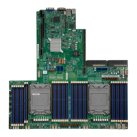
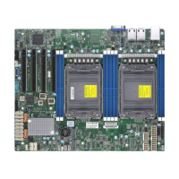
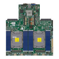
Visual representation of the motherboard layout for reference.
Detailed diagram showing the placement of components and connectors on the motherboard.
Provides a brief overview of essential connectors and indicators on the motherboard.
A table summarizing jumpers, LEDs, and connectors with their descriptions.
Comprehensive overview of the motherboard's key hardware specifications and capabilities.
Details the processor support and capabilities of the motherboard.
Information on memory support, including type, speed, and capacity.
Lists and describes the available PCIe and M.2 expansion slots.
Lists and describes various input/output devices and ports.
Details the various USB ports and headers available on the motherboard.
Information about the AMI BIOS features and support.
Explains ACPI power management features and system power settings.
Details features like TPM and Root of Trust for system security.
Offers procedures to diagnose and resolve system issues.
Outlines steps to follow before contacting Supermicro technical support.
Provides instructions for safely removing and installing the motherboard battery.
Troubleshooting steps for when the system does not power on.
Troubleshooting steps for when the system powers on but displays no video.
Steps to diagnose and resolve issues where the system fails to boot or POST.
Guidance on troubleshooting memory compatibility and installation issues.
Troubleshooting guide for system instability during or after OS installation.
Introduces the AMIBIOS setup utility for system configuration.
Describes the initial screen and basic settings within the BIOS utility.
Details advanced configuration options available in the BIOS setup.
Details system security settings, including passwords and secure boot.
Covers boot settings, order priorities, and boot modes.
Options for saving changes and exiting the BIOS setup utility.
Provides precautions for handling static-sensitive components to prevent damage.
Step-by-step guide for installing the CPU and heatsink module.
Guide for physically mounting the motherboard into the chassis.
Information on memory compatibility and the procedure for installing DIMMs.
Step-by-step guide for installing DIMM modules into the memory slots.
Instructions for safely removing DIMM modules.
Identifies and describes the ports located on the motherboard's rear I/O panel.
Details the various USB ports and headers on the motherboard.
Explains the dual function of the UID/BMC Reset switch and associated LEDs.
Describes the front control panel header (JF1) for chassis buttons and LEDs.
Details the Power Button and Reset Button functions and pin definitions.
Explains the status and meaning of Power Fail and Information LEDs.
Describes NIC LEDs, UID switch, BMC Reset, and HDD LED connections.
Details the Onboard Power LED and NMI Button functionality.
Details various motherboard connectors and their functions.
Covers power connectors, including ATX and 8-pin 12V.
Describes the eight 4-pin fan headers and their pin definitions.
Explains the JTPM1 header for connecting a Trusted Platform Module.
Describes the JRK1 header for installing a VROC RAID Key for NVMe RAID.
Details the various SATA ports on the motherboard.
Explains how jumpers work and their function on the motherboard.
Instructions for clearing the CMOS settings using the JBT1 jumper.
Explains how to enable or disable onboard LAN ports using the JPL1 jumper.
Explains the function of various LEDs on the motherboard.
Describes the LEDs for LAN1 and LAN2 ports indicating activity and link speed.
Describes the Onboard Power LED (LE3) and its status.
Provides precautions for handling static-sensitive components to prevent damage.
Step-by-step guide for installing the CPU and heatsink module.
Step-by-step instructions for assembling the processor and carrier.
Instructions on how to prepare the CPU socket by removing the protective cover.
Steps to prepare the heatsink and CPU socket for PHM installation.
Detailed procedure for attaching the PHM to the CPU socket.
Guide for physically mounting the motherboard into the chassis.
Information on memory compatibility and the procedure for installing DIMMs.
Describes the SlimSAS connectors for high-speed PCIe storage devices.
Explains the JNSCI header for connecting a Network Interface Card to the BMC.
Offers procedures to diagnose and resolve system issues.
Addresses common user questions about memory and BIOS updates.
Troubleshooting steps for when the system powers on but displays no video.
Steps to diagnose and resolve issues where the system fails to boot or POST.
Guidance on troubleshooting memory compatibility and installation issues.
Troubleshooting guide for system instability during or after OS installation.
Introduces the AMIBIOS setup utility for system configuration.
Details advanced configuration options available in the BIOS setup.
Explains how to configure and view system event logs.
Covers configuration settings for the Baseboard Management Controller.
Details system security settings, including passwords and secure boot.
Covers boot settings, order priorities, and boot modes.
Details about AMI BIOS checkpoint codes.
Guide for installing the Microsoft Windows Operating System, including RAID setup.
Instructions for downloading and installing system drivers from the Supermicro website.
Overview of SuperDoctor 5 for system monitoring and management.
Information about the Baseboard Management Controller (BMC) and related BIOS settings.
Instructions on how to log into the BMC for the first time.
Warnings and instructions related to handling and replacing batteries.
| Brand | Supermicro |
|---|---|
| Model | X12DPi-N6 |
| Category | Motherboard |
| Language | English |