48
Super X12DPi-N6/X12DPi-NT6 User's Manual
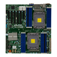
Image to be updated
UID/BMC Reset Switch (JUIDB1)
Pin Denitions
Pin# Denition
1 Ground
2 Ground
3 Button In
4 Button In
UID (Unit Idencation)/BMC Reset Switch and UID/BMC Reset LED Indicators
A UID LED/BMC Reset switch (JUIDB1) is located on the rear side of the motherboard. This
switch has dual functions. It can be used to identify a system unit that is in need of service,
and it can also be used to reset the BMC settings.
When functioning as a BMC reset switch, JUIDB1 will trigger a cold reboot when the user
presses and holds the switch for 6 seconds. It will also restore the BMC to the manufacturer's
default when the user presses and holds the switch for 12 seconds.
When functioning as a UID LED switch, JUIDB1 will turn both rear UID LED (LE6) and front
UID LED (Pin 7/Pin 8 of JF1) on and off when the user presses the switch on/off.
To achieve these dual purposes, the UID LED/BMC Reset switch works in conjunction with
the BMC Heartbeat LED (LEDM1) and front/rear UID LEDs. Please note that UID can also be
triggered via BMC on the motherboard. For more details on the UID LEDs and BMC LEDs,
refer to the tables below. Also, refer to the BMC User's Guide posted on our website at http://
www.supermicro.com for more information on BMC.
1
1. UID LED/BMC Reset Switch
2. Rear UID LED (LE6)
3. Front UID LED (Pins 7 & 8 of JF1)
4. BMC Heartbeat LED (LEDM1)
1
UID/BMC Reset Switch (JUIDB1)
Features & Settings
When Used as a UID LED Switch When Used as a BMC Reset Switch
Work w/Rear UID LED (LE6) & Front UID LED (JF1: Pins 7& 8) Work with BMC Heartbeat LED (LEDM1)
Rear UID LED LE6 Blue: Unit identied BMC Heartbeat LED LEDM1 Green Blinking: BMC Normal
Front UID LED Pins 7 & 8 (JF1) Blue: Unit identied BMC Reset: Press
& hold the switch
(JUIDB1) 6 seconds
LEDM1: Solid green: during reboot
Press the switch (JUIDB1) to turn on and off both rear
and front UID LED indicators;
Triggering a cold reboot; LED: solid
green on during cold reboot
BMC Reset: Press
& hold the switch
(JUIDB1) 12 seconds
LEDM1: Solid green: during BMC reset
BMC: Reset to the manufacturer's
default; LED solid on during BMC Reset
C
MAC CODE
BIOS
LICENSE
BMC CODE
JS3 JS1
BMC
BMC
Firmware
BIOS
JM2_1
JF1
LAN1
LAN2
FAN3FAN4
JUSBRJ45
JNCSI
JUIDB1
FANA
F
AN6
FAN2FAN1
JPI2C1
LE4
LE6
JRK1
(Front) VGA
JBT1
JSTBY1
JPME1
JIPMB1
JNVI2C
JPWR4
JPWR2
S-SGPIO
SATA5
SATA6
JPWR3
JLAN2
JLAN1
UID LED
JS2
M.2 Slot
TPM/Port80
PCH
LED
PWR
BMC Heartbeat LED
BMC_LAN/USB7/8(3.0)
P1_NVME2/3
P1_NVME0/1
I-SATA0~3 I-SATA4~7
USB6(3.0) USB4/5(3.0)
USB2/3
(3.0)
USB0/1
(2.0)
S-SATA4 S-SATA5
S-SATA0~3
VGA
COM2
COM1
CMOS CLEAR
UID/BMC
P1-DIMMG1
P1-DIMMF1
P1-DIMME1
P1-DIMMH1
P2-DIMMG1
P2-DIMME1
P2-DIMMF1
P2-DIMMH1
CPU2
CPU1
CPU1 SLOT1 PCIe 4.0 X8
CPU1 SLOT2 PCIe 4.0 X16
CPU1 SLOT3 PCIe 4.0 X16
CPU2 SLOT4 PCIe 4.0 X16
CPU2 SLOT5 PCIe 4.0 X16
CPU2 SLOT6 PCIe 4.0 X8
P1-DIMMB1
P1-DIMMA1
P1-DIMMD1
P1-DIMMC1
P2-DIMMC1
P2-DIMMD1
P2-DIMMB1
P2-DIMMA1
LE3
JL1
BAR CODE
VROC
JVGA
JFP2
LAN CTRL2
JTPM-1
RAID KEY-1
Front Panel CTRL
P2-DIMMB2
P1-DIMMB2
CPLD
FAN5
REV:1.00
X12DPi-N(T)6
LAN CTRL1
(*X12DPI-N6)
X12DPI-NT6
BT1
Battery
Reset
MH15
MH16
NVME
JPL1
LEDM1
2
3
4
Power Button
UID LED
Reset Button
HDD LED
PWR LED
3.3V Stby/
UID SW
Ground
19
Ground
20
1 2
Ground
Power Fail LED
NIC2 Active LED
NMI
3.3V
OH/PWR Fail/Fan Fail LED
3.3V
JF1
X
3.3V Stby
3.3V Stby
NIC1 Active LED
X
3
 Loading...
