42
Super X12DPi-N6/X12DPi-NT6 User's Manual
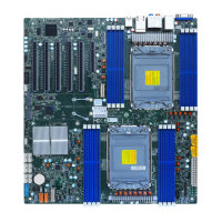
DIMM Installation
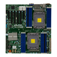
1. Insert the desired number of DIMMs into the memory
slots based on the recommended DIMM population tables
in the previous section. Locate DIMM memory slots on
the motherboard as shown on the right.
2. Push the release tabs outwards on both ends of the
DIMM slot to unlock it.
Release Tabs
Push both ends
straight down into
the memory slot.
C
MAC CODE
BIOS
LICENSE
BMC CODE
JS3 JS1
BMC
BMC
Firmware
BIOS
JM2_1
JF1
LAN1
LAN2
FAN3FAN4
JUSBRJ45
JNCSI
JUIDB1
FANB
FANA
F
AN6
FAN2FAN1
JPI2C1
LE4
LE6
JRK1
(Front) VGA
JBT1
JSTBY1
JPME1
JIPMB1
JNVI2C
JPWR4
JPWR2
S-SGPIO
SATA5
SATA6
JPWR3
JLAN2
JLAN1
UID LED
JS2
M.2 Slot
TPM/Port80
PCH
LED
PWR
BMC Heartbeat LED
BMC_LAN/USB7/8(3.0)
P1_NVME2/3
P1_NVME0/1
I-SATA0~3 I-SATA4~7
USB6(3.0) USB4/5(3.0)
USB2/3
(3.0)
USB0/1
(2.0)
S-SATA4S-SATA5
S-SATA0~3
VGA
COM2
COM1
CMOS CLEAR
UID/BMC
P1-DIMMG1
P1-DIMMF1
P1-DIMME1
P1-DIMMH1
P2-DIMMG1
P2-DIMME1
P2-DIMMF1
P2-DIMMH1
CPU2
CPU1
CPU1 SLOT1 PCIe 4.0 X8
CPU1 SLOT2 PCIe 4.0 X16
CPU1 SLOT3 PCIe 4.0 X16
CPU2 SLOT4 PCIe 4.0 X16
CPU2 SLOT5 PCIe 4.0 X16
CPU2 SLOT6 PCIe 4.0 X8
P1-DIMMB1
P1-DIMMA1
P1-DIMMD1
P1-DIMMC1
P2-DIMMC1
P2-DIMMD1
P2-DIMMB1
P2-DIMMA1
LE3
JL1
BAR CODE
VROC
JVGA
JFP2
LAN CTRL2
JTPM-1
RAID KEY-1
Front Panel CTRL
P2-DIMMB2
P1-DIMMB2
CPLD
FAN5
REV:1.00
X12DPi-N(T)6
LAN CTRL1
(*X12DPI-N6)
X12DPI-NT6
BT1
Battery
Reset
MH15
MH16
NVME
JPL1
LEDM1
DIMM Removal
Press both release tabs on the ends of the DIMM module to unlock it. Once the DIMM module
is loosened, remove it from the memory slot.
Warning! Please do not use excessive force when pressing the release tabs on the ends of the
DIMM socket to avoid causing any damage to the DIMM module or the DIMM socket. Please
handle DIMM modules with care. Carefully follow all the instructions given on Page 1 of this
chapter to avoid ESD-related damages done to your memory modules or components.
3. Align the key of the DIMM module with the receptive point on the memory slot.
Key
4. Align the notches on both ends of the module against the receptive points on the ends
of the slot.
5. Push both ends of the module straight down into the slot until the module snaps into
place.
6. Press the release tabs to the lock positions to secure the DIMM module into the slot.
Notches
 Loading...
