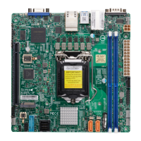
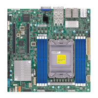
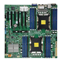
3
Preface
Preface
About This Manual
This manual is written for system integrators, IT technicians and knowledgeable end users.
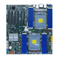
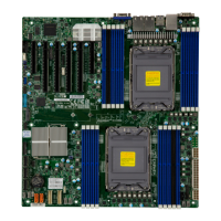
It provides information for the installation and use of the X12DPi-N(T)6 motherboard.
About This Motherboard
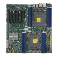
The Supermicro X12DPi-N6/X12DPi-NT6 supports dual 3rd Gen Intel® Xeon® Scalable
Processors (in Socket P+ LGA 4189) with up to 40 CPU cores and a thermal design power
(TDP) of up to 270W. Built with the Intel C621A chipset, the X12DPi-N(T)6 supports up
to 4TB 3DS LRDIMM/LRDIMM/3DS RDIMM/RDIMM DDR4 ECC memory with speeds of
3200/2933/2666MHz in 16 DIMM slots and up to 4TB of Intel® Optane™ PMem 200 Series
with speeds of up to 3200MHz in two additional slots (Note 2 below). This motherboard
features superior IO expandability, which includes six PCIe 4.0 slots, two PCIe 4.0 x8 NVMe
SlimSAS ports (with four connections), 14 SATA 3.0 ports, one M.2 slot, and nine USB ports.
It also offers the most advanced data protection capability that encompasses TPM (Trusted
Platform Module) and RoT (Root of Trust) support. The X12DPi-N(T)6 is optimized for high-
performance, high-end computing platforms and is ideal for big data, enterprise applications.
Please note that this motherboard is intended to be installed and serviced by professional
technicians only. For processor/memory updates, please refer to our website at http://www.
supermicro.com/products/.
Note 1: The Intel
®
Optane
TM
Persistent Memory (PMem) 200 Series are supported by
the 3rd gen Intel Xeon Scalable (83xx/63xx/53xx/4314 Series) Processors.
Note 2: P1-DIMMB2 and P2-DIMMB2 memory slots are reserved for PMem 200 Se-
ries only.
Note 3: Memory speed support depends on the processors used in the system.
Conventions Used in the Manual
Special attention should be given to the following symbols for proper installation and to prevent
damage done to the components or injury to yourself:
Warning! Indicates high voltage may be encountered while performing a procedure.
Warning! Indicates important information given to prevent equipment/property damage
or personal injury.
Important: Important information given to ensure proper system installation or to
relay safety precautions.
Note: Additional Information given to differentiate various models or to provide in-
formation for proper system setup.
 Loading...
