DELroloCsutatSnoitpircseD
forebmuN
DEL
rewoPneerGnOnorewoP1
tseTwolleYnO
rorretsetpooL
srucco
1
.tcA/deepS
neerG
nO
fospbM001
tropdetcennoc
)8-1(8
gnihsalF
atadrofspbM001
gniviecer
wolleY
nO
fospbM01
tropdetcennoc
gnihsalF
atadrofspbM01
gniviecer
.loC/XDFneerG
nO
fosutatsxelpuD-lluF
tropdetcennoc
)8-1(8
gnihsalF
fosrucconoisilloC
M001roM01
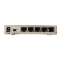
1. Uplink
The Uplink port is used to connect to other
switches or hubs. The Uplink port is shared with
the port #1.
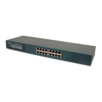
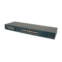
2. RJ-45 Ports
Eight N-Way Mini RJ-45 STP ports all come with
auto-negotiation and operate at 100/10Mbps for
connection to servers and hubs. All ports can be
configurated for Full/Half-Duplex mode.
3. Power Connector
For the external 7.5V DC power adapter that
connects to power outlet.
Rear Panel
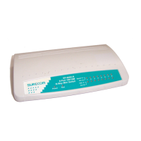
LED Indicators
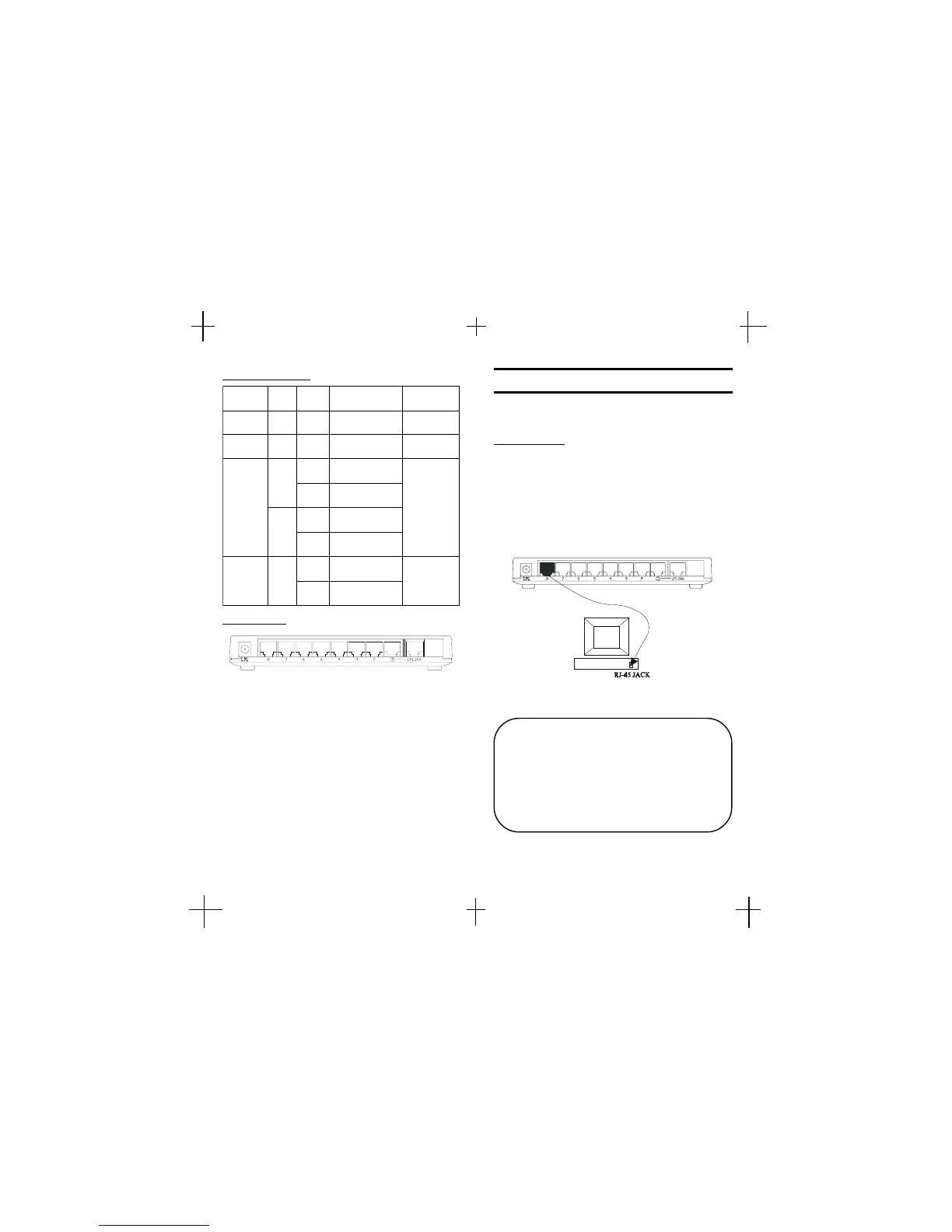
The following figures illustrate the connections of
8-Port N-Way Mini Switch.
PC to Switch
A PC can be connected to the 8-Port N-Way Mini
Switch via a two-pair Category 3/4/5 UTP/STP
straight cable. The PC (equipped with a RJ-45 100/
10Mbps jack) should be connected to any of eight
ports.
The 8-Port N-Way Mini Switch
Note: The LED indicators for PC con-
nection are dependant on the LAN card
capabilities. If LED indicators are not
illuminated after making a proper
connection, check the PC LAN card, the
cable, the N-Way Mini Switch conditions
and the connections.
!"
Network Connection
 Loading...