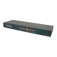
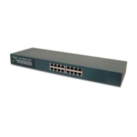
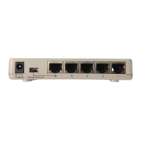
Rear Panel
LED Indicators
1. Power
This indicator operates when the Switch is turned on. If this indictor is
not lit, check the DC power connector to ensure proper insertion of the
power cord and that the power switch is turned ON.
2. Link/Act
These LED indicators are lighted up when there is a secure connection
(or link) to a device at any of the 16 ports. The LED indicators blink whenever
there is reception or transmission (i.e. Activity/ACT.) of data occurring
at any of the 16 ports.
3. FDX/Col
This LED indicator is lighted up when a respective port is in full-duplex
(FDX) mode. Otherwise, it is OFF for half-duplex (HDX) operations. It
blinks when collisions are occurring on the respective port.
The LED indicators of the Switch include Power, Link/Act (Link Activity),
FDX/COL. (Full-Duplex/Collision) and 100Mbps link speed status.
4. 100
This LED lights when the transmission rate is 100Mbps. It is OFF when
the transmission rate is 10Mbps or no linking.
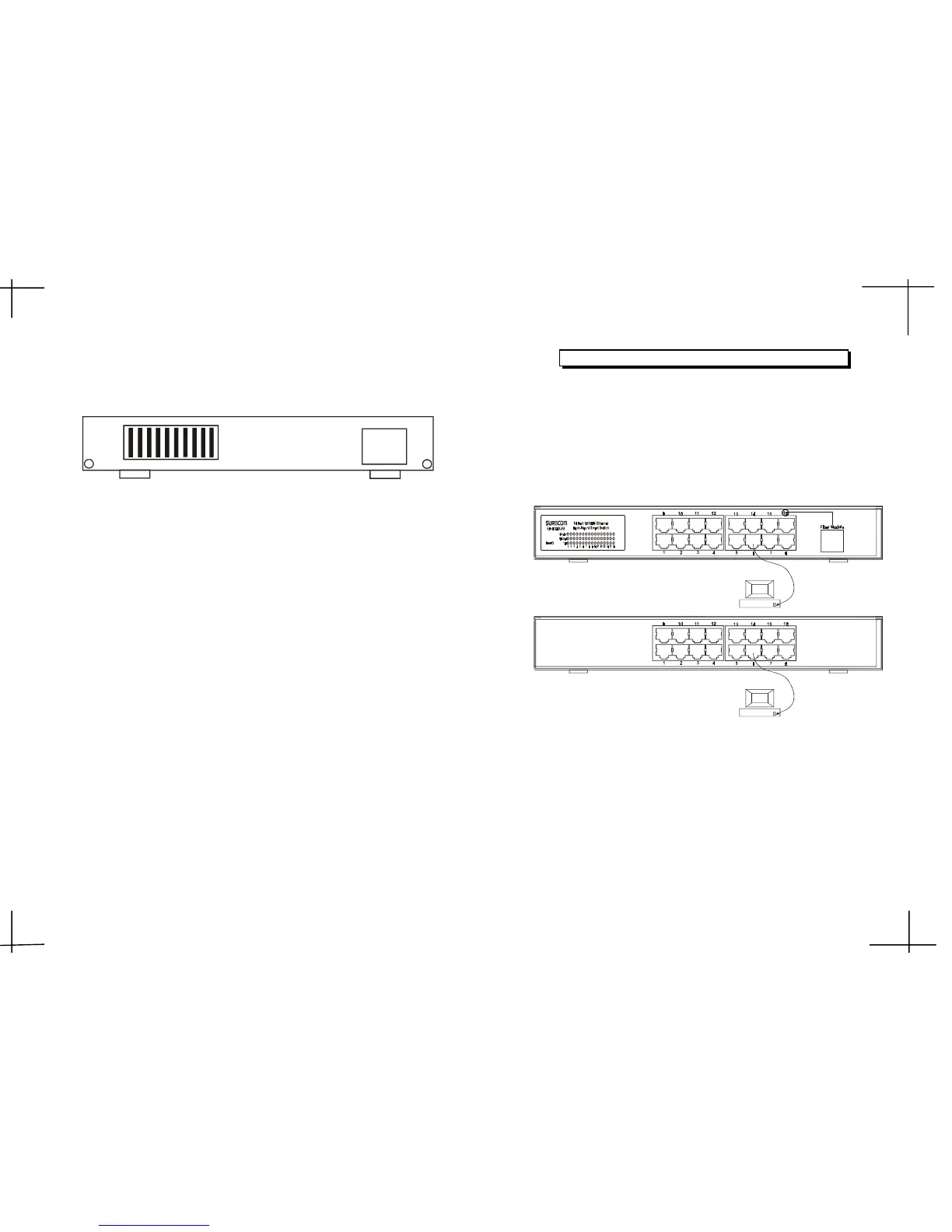
Network Connections
Following describes how to connect this Switch to your Fast Ethernet
network.
Switch to PC
A PC can be connected to the Switch via a twisted-pair Category 3, 4,5
for 10Mbps and category 5 for 100Mbps.(UTP/STP straight cable or cross-
over cable) The PC (equipped with a RJ-45 10/100Mbps jack) should be
connected to any of sixteen ports.
The LED indicators for PC connection are dependant on the LAN card
capabilities. If LED indicators are not illuminated after making a proper
connection, check the PC LAN card, the cable, Switch conditions and
connections.
The following are LED indicator possibilities for a PC to Switch connection:
1. The Link/ACT. LED indicator illuminates upon hookup.
2. The FDX/COL. LED indicator depends upon LAN card capabilities.
3. The 100 LED indicator comes on for a 100Mbps connection and stays
off for 10Mbps connection.
RJ- 45 JACK
3 4
90~264VAC
47~63Hz
DIP 1~10
EP-816CX/DX/DX-FS
RJ- 45 JACK
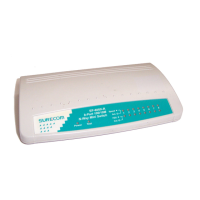
EP-816DX-FS
EP-816CX/DX
 Loading...