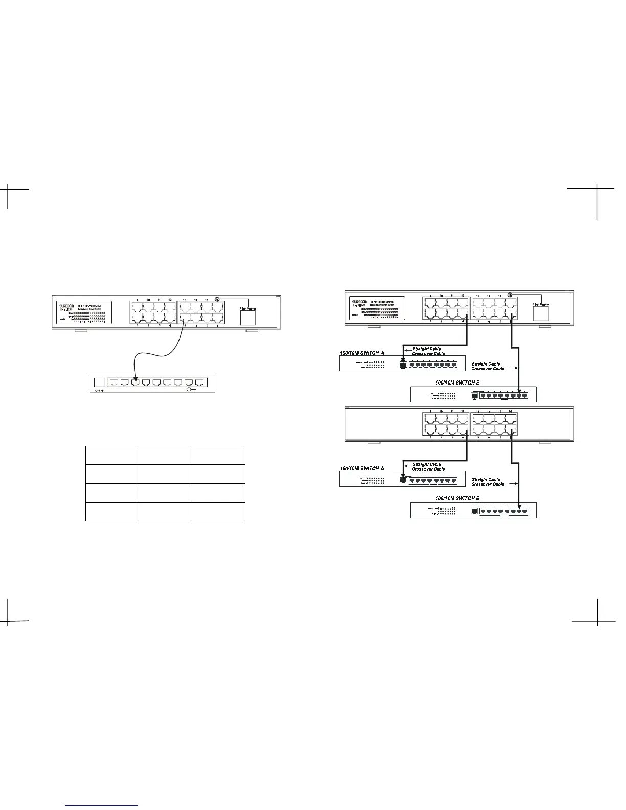
Switch to Hub
Switch to Switch (Other Devices)
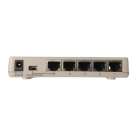
DC 7.5V
8765432
Up-L in k
1
5 6
EP-816DX-FS
EP-816CX/DX
the fiber cable.
When the fiber module connects to the fiber board, but it doesnt connect to
After the fiber module connects to the fiber board, you have to restart
deLroloCsutatS
kniLneerGffO
lluFneerGnO
001neerGnO
Led Status
the power again.
A 10 BASE-T Hub can be connected to the switch via a twisted-pair Category
3,4,5 UTP/STP straight cable or crossover cable. And the 100BASE-TX Hub
should be connected via Category 5 UTP/STP straight cable or crossover cable.
The Switch can be connected to another switch or other devices (routers,
bridges, etc.)via a twisted-pair Category 5 UTP/STP straight or crossover
cable for 100Mbps connection.