Smart Function
SF-XD/XD/XC618-PE
:sdradnatStenrehtET-ESAB013.208EEEI
tenrehtEtsaFXF/XT-ESAB001u3.208EEEI
xelpuD-lluFroflortnocwolfx3.208EEEI
noitaitogen-otuataW-N3.208dtSEEEI/ISNA
tnerapsnarT:sepytemarF3.208EEEI
xelpuD-flaHroflortnocwolferusserPkcaB
:locotorPDC/AMSC
:ygolopoTratS
noissimsnarT
:dohteMdrawrof-dna-derotS
:etaRrefsnarT
:tenrehtE
:tenrehtEtsaF
)xelpuD-lluF(spbM02;)xelpuD-flaH(spbM01
)xelpuD-lluF(spbM002;)xelpuD-flaH(spbM001
:aideM
:T-ESAB01
:XT-ESAB001
:XF-ESAB001
;)m001htgnelelbac.xaM(5,4,3.taCPTU
;)m001htgnelelbac.xaM(5.taCPTU
citporebifedom-itlumnorcim521/5.26,05
citporebifedom-elgnisnorcim521/9,8
:stroPfo.oNstroP54-JRspbM01/00161
gnisuoH
:lairetaMnorI
:reffuBMARecivedrepstibM1latoT
gniretliFtekcaP
gnidrawroF/
:etaR)spbM01&spbM001rof(troprepdeeps-eriW
:rewoP)CDA5/V3.3(zH36-74,V462-09CA
:noitpmusnoCW8
:erutarepmeT
:gnitarepO
:egarotS
0
0
54~C
0
C
0
0
06~C
0
C
:ytidimuH
:gnitarepO
:egarotS
%09~%01
%59~%5
:ecnamrofnoCAssalCkraMEC,AssalCCCF
Technical Specifications
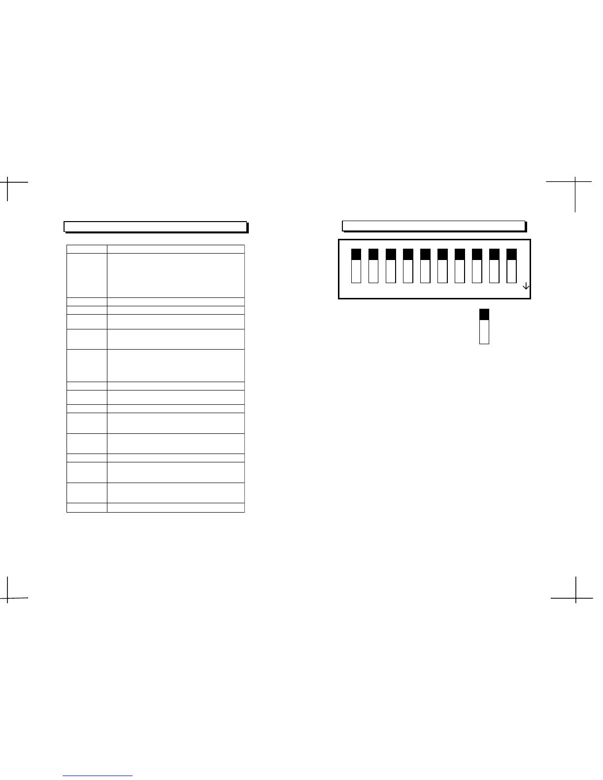
1 2 3
4
5 6 7 9 10
1: Enable the VLAN function on each port.
0: Disable the VLAN function on each 16 ports. (default)
DIP 1:
Ext. Port#1,12 as one group, Port#2,12 as one group....
DIP 2:
1: Enable port trunk 0 which consists of ports 5,6,13,14
DIP 3:
DIP 4:
7 8
Enable Port Based VLAN configuration function:
VLAN topology type selection:
1:Select 15 VALNs (port#1~11,13~16) with 1 overlapping port
(port#12) topology.
Enable Port Trunk 0:
Enable Port Trunk 1:
OFF:0
ON:1
0
1
DIP 8
ON
.0: Disable port trunk 0
1: Enable port trunk 1 which consists of ports 7,8,15,16
Ext. Port#1,4,12 as one group, Port#2,4,12 as one group....
0: Disable port trunk 1
0:Select 14 VLANs(port#1~3,5~11,13~16)with 2 overlapping ports
(port#4,12)topology.(default)