1. Full/Half-Duplex Mode Selection
This dip switch is for full/half duplex mode selection in fiber module option.
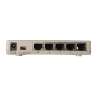
2. Fiber Connector
Extends the workgroup distance up to 2,000 meters.
3. Uplink Port
Allows using regular straight-through cables to connect this Switch to other
Switch or Hubs normal port.
4. RJ-45 Ports
Uses these twenty-four ports to connect to another Switches or Hubs. Each port
uses auto-negotiation for automatic speed and mode selection.
Note: The Fiber Connector, the Uplink port and the port #1 share
with each other. Ensure choosing only one port from the three
to attach to another device.
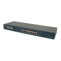
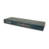
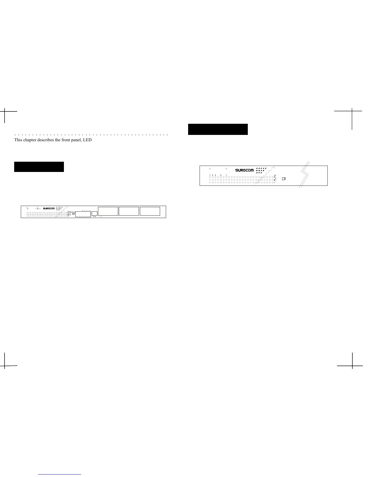
The front panel of the Switch consists of 24 (100/10Mbps MDI-X) ports, 1 Uplink
(MDI) and 1 fiber slide-in ports.
2. Hardware
○○○○○○○○○○○○○○○○○○○○○○○○○○○○○○○○○○○○○○○○○○○○
This chapter describes the front panel, LED indicators, and rear panel on the Switch.
Figure 2-1: Front Panel
2-2
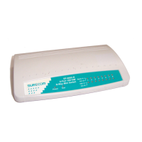
The LED indicators are all located on the front panel which include one Power, one
Fiber Slide-in, one Link/Act., one FDX/Col,and one Speed indicator per port.
Figure 2-2: LED indicators
1. Power
The LED lights when the Switch is powered on. If the LED , fails to light, checkThe LED lights when the Switch is powered on. If the LED , fails to light, check
The LED lights when the Switch is powered on. If the LED , fails to light, checkThe LED lights when the Switch is powered on. If the LED , fails to light, check
The LED lights when the Switch is powered on. If the LED , fails to light, check
the AC power connector to ensure proper insertion of the power cord and thatthe AC power connector to ensure proper insertion of the power cord and that
the AC power connector to ensure proper insertion of the power cord and thatthe AC power connector to ensure proper insertion of the power cord and that
the AC power connector to ensure proper insertion of the power cord and that
the power switch is turned ON.the power switch is turned ON.
the power switch is turned ON.the power switch is turned ON.
the power switch is turned ON.
2.2.
2.2.
2.
Fiber Slide-inFiber Slide-in
Fiber Slide-inFiber Slide-in
Fiber Slide-in
The LED lights to indicate that the optional fiber slide-in module is chosen toThe LED lights to indicate that the optional fiber slide-in module is chosen to
The LED lights to indicate that the optional fiber slide-in module is chosen toThe LED lights to indicate that the optional fiber slide-in module is chosen to
The LED lights to indicate that the optional fiber slide-in module is chosen to
operate the Switch.operate the Switch.
operate the Switch.operate the Switch.
operate the Switch.
3.3.
3.3.
3.
Link/ActLink/Act
Link/ActLink/Act
Link/Act
These LEDs light upThese LEDs light up
These LEDs light upThese LEDs light up
These LEDs light up green
to indicate that a valid link is established. These LEDs to indicate that a valid link is established. These LEDs
to indicate that a valid link is established. These LEDs to indicate that a valid link is established. These LEDs
to indicate that a valid link is established. These LEDs
flash whenever data packets are transmitting or receiving.flash whenever data packets are transmitting or receiving.
flash whenever data packets are transmitting or receiving.flash whenever data packets are transmitting or receiving.
flash whenever data packets are transmitting or receiving.
4. FDX/Col
These LEDs light upThese LEDs light up
These LEDs light upThese LEDs light up
These LEDs light up green
to show the ports are operating in full-duplex (FDX)to show the ports are operating in full-duplex (FDX)
to show the ports are operating in full-duplex (FDX)to show the ports are operating in full-duplex (FDX)
to show the ports are operating in full-duplex (FDX)
mode. These LEDs flash whenever collision is detected on the netwok segments.mode. These LEDs flash whenever collision is detected on the netwok segments.
mode. These LEDs flash whenever collision is detected on the netwok segments.mode. These LEDs flash whenever collision is detected on the netwok segments.
mode. These LEDs flash whenever collision is detected on the netwok segments.
5. Speed
These LEDs light when the ports run at 100Mbps. These LEDs are OFF when theyThese LEDs light when the ports run at 100Mbps. These LEDs are OFF when they
These LEDs light when the ports run at 100Mbps. These LEDs are OFF when theyThese LEDs light when the ports run at 100Mbps. These LEDs are OFF when they
These LEDs light when the ports run at 100Mbps. These LEDs are OFF when they
run at 10Mbps or are not connected.run at 10Mbps or are not connected.
run at 10Mbps or are not connected.run at 10Mbps or are not connected.
run at 10Mbps or are not connected.
LED Indicators
2-12-1
2-12-1
2-1
Front Panel
13 14 15
1
234
5678
9 101112
16 17 18 19 20
21 22 23 24
1
23 54 6 7 8 9 10 11 12 13 14 15 16 17 18 19 20 21 22 23 24
EP -824DX -CS
24
-Port 100/10M N-Way 19" Rack-Mount Smart Switch
 Loading...