5
2 Features
• Unsurpassed SurgeX
®
power conditioning and surge protection
• Incorporates SurgeX ICE™ Inrush Current Elimination Circuitry
• All time delays and functions easily programmed from the front panel
• Accepts both DC voltage and contact closure type inputs
• Two or more units can be ganged or cascaded together to handle larger systems
• Programmable auxiliary relay output can be used to control other SurgeX
®
products
• Built-in AC Voltmeter
• Over-ride input can be used to force unit off or force unit on
• Optional password can be used to prevent unauthorized access to set-up information
• Adjustable under-voltage and over-voltage shut-down
• Programmable 12V dc output can be used to drive LEDs or a small relay
• Optional restore after power failure feature
• Auxiliary relay or 12V dc output can be programmed to provide confirmation feedback
3 Installation
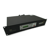
The SurgeX SX2120-SEQ is designed to be installed in a 19 inch equipment rack and requires
two units (2-U) of rack space. Connect power to the unit by plugging the cord into a 120V ac, 20
amp receptacle. The SEQ cannot be plugged into a 15 amp receptacle. If a 120V, 20 amp branch
circuit is not available, you will need to have one installed by a licensed electrical contractor.
3.1 120 Volt Connections
The SX2120-SEQ has a total of 14 receptacles: three sequenced banks of four, and two always
on. Each receptacle is rated for a maximum load of 15 amps but the total load of the SEQ must
not exceed 20 amps. Plug the equipment cords into the receptacle banks as needed to turn on
equipment in the required sequence. The “always on” receptacles provide power as long as
power is supplied to the SEQ. Bank “A” always powers up first and off last.
3.2 Remote Control Connections
Remote connections are wired to the green 7-pin plug-in Phoenix terminal block on the rear of
the unit next to the power cord. The terminal block itself is provided in the accessory bag that
you will find in the shipping box. After you have made the connections to the terminal block,
plug it into the connector on the rear of the unit. Never solder (tin) wires before inserting in a
terminal block – solder creeps and you will eventually have loose connections!
The connections are shown below: