YH4
GRAND
VITARA
7B1-38 AUTOMATIC TRANSMISSION (4 A/T)
“5”
“4”
DIAGNOSTIC FLOW TABLE B-4 “POWER” LIGHT CIRCUIT CHECK
(“POWER” LIGHT COMES ON STEADILY)
WIRING DIAGRAM – Refer to Table B-3 in this section.
TROUBLESHOOTING
STEP ACTION YES NO
1 Check Power/Normal Change Switch Position.
Is switch button at Normal position?
Go to Step 2. Set Power/Normal
change switch at
Normal position.
2 Check Lamp Circuit for Short.
1) Turn ignition switch OFF and disconnect PCM
connectors.
2) Turn ignition switch ON.
Does “POWER” lamp come ON steadily?
“Gr/Bl” circuit
shorted to ground.
Go to Step 3.
3 Check Power/Normal Change Switch Circuit.
1) Check resistance between terminal E61-31
(G16/J20 engines) or E61-9 (H25 engine) of
disconnected PCM connector and body ground with
P/N change switch OFF.
Is continuity indicated?
Go to Step 4. Check PCM ground
circuit for open.
If ground circuit is
OK, substitute a
known-good PCM
and recheck.
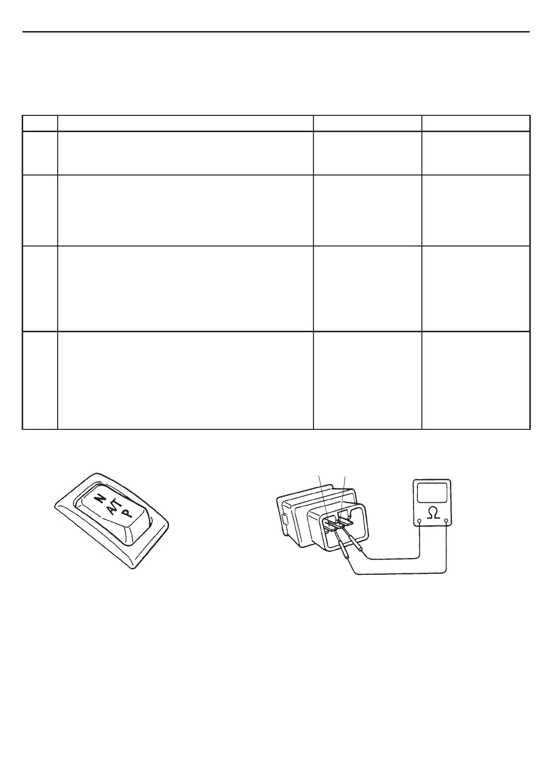
4 Check Power/Normal Change Switch for Operation.
1) Remove Power/Normal change switch.
2) Check continuity between switch terminals “4” and
“5” under each condition below.
Normal position: No continuity
Power position: Continuity.
Is check result satisfactory?
“Or/Bl” circuit
shorted to ground.
Replace Power/
Normal change
switch.
Fig. for Step 1. Fig. for Step 4.
 Loading...

