YH4
GRAND
VITARA
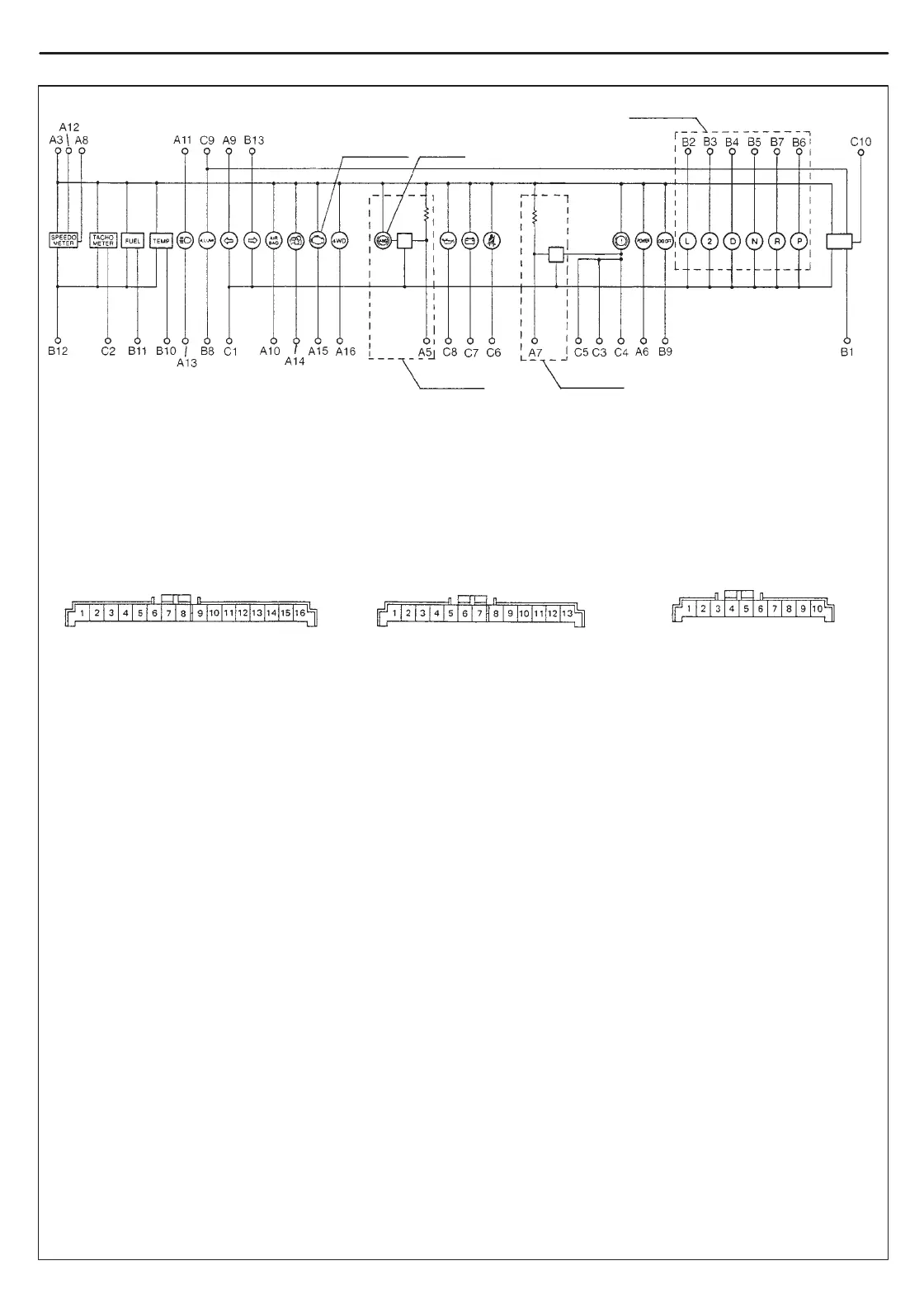
1. To door switch (driver side) B/Bl
2. To transmission range switch G/Bl
(A/T vehicle only, if equipped) L
3. To transmission range switch G/O
(A/T vehicle only, if equipped) 2
4. To transmission range switch Y/G
(A/T vehicle only, if equipped) D
5. To transmission range switch O/Bl
(A/T vehicle only, if equipped) N
6. To transmission range switch O/G
(A/T vehicle only, if equipped) P
7. To transmission range switch R
(A/T vehicle only, if equipped) R
8. To ground B
9. To PCM (A/T vehicle only) W/ B
10. To ECT sensor Y / W
11. To fuel level gauge Bl/ W
12. To ground B/ Y
13. To combination switch G/Y
NOTE:
Terminal arrangement of coupler viewed from harness side.
Coupler A Coupler B Coupler C
Coupler A Coupler B Coupler C
1. Blank ——
2. Blank ——
3. To ignition switch B/W
4. Blank ——
5. To ABS control module Bl/O
(if equipped)
6. To PCM (A/T vehicle only) Gr/Bl
7. To ABS control module Br
(if equipped)
8. To VSS Bl/Y
9. To combination switch G/R
10. To SDM (if equipped) Y/G or Bl
11. To main fuse W / Bl
12. To fuse box W
13. To combination switch R
14. To ECM (PCM for A/T vehicle) V
(if equipped)
15. To ECM (PCM for A/T vehicle) V/Y
16. To ECM (PCM for A/T vehicle) O/B
(if equipped)
1. To ground B
2. To ECM (PCM for A/T vehicle) Br
3. To ignition switch (if equipped) V/R
4. To brake fluid level switch R /B
5. To parking brake switch V
6. To seat belt switch (if equipped) Gr/R
7. To generator W/ R
8. To oil pressure switch Y/B
9. To combination switch R/Y
10. To ignition switch (if equipped) Bl/R
or CHECK
or ENGINE
or ABS
if equipped
if equipped
if equipped
INSTRUMENTATION/DRIVER INFORMATION 8C-3
 Loading...

