EasyManua.ls Logo

Suzuki LTR450 - User Manual

Suzuki LTR450
2 pages
Print Icon
To Next Page IconTo Next Page
Loading...
INSTALLATION INSTRUCTIONS
SUZUKI
TOOLS NEEDED
- 8 & 10 mm Socket or T-handle
- Slotted Screwdriver
- Less than 2 hours
Suzuki LTR450
Fuel Injected Models
INTRODUCTION: Congratulations on your purchase of the
Fuelpak Fuel Management System for fuel injected Suzuki LTR
450 models. Please take the time to read the entire instruction
manual before attempting to install. DO NOT adjust Fuelpak
until you have thoroughly read the instruction manual and the
unit is fully installed. If you have questions, please call Fuelpak
technical support at (562) 921-0071.
SUMMARY: To achieve the optimum performance from
your application, it is recommended that you install a high
performance air filter in conjunction with this unit. Fuelpak
will be installed in-line with the factory injector wiring harness and
the throttle position sensor. The unit will be mounted under the seat.
(Important Note): Fuelpak maps for the LTR450 were created with a
White Brothers Power Pro performance module installed. The included
Power Pro unit must be used in conjunction with the Fuelpak for proper
function. Failure to do so will result in poor performance and may cause
engine damage.
1. Be sure that key is in the off position, then remove seat.
2. Referring to figure 1, remove (4) push pins and (1) 10mm bolt.
Repeat for opposite side. Push pins that are accessible from the back
can be popped out by pushing on the pin from the back side.
Push pins with flanged pin heads can be gently pried up with a
slotted screwdriver.
3. Remove fuel cap and tank cover. Reinstall fuel cap.
4. Clean Fuelpak mounting location with alcohol and allow to dry.
Referring to figure 2, mount Fuelpak as shown with supplied Velcro.
Route harness as shown, between airbox and subframe, and
underneath subframe cross brace.Gently pull up and out on
subframe side cover and attach harness to subframe with included
zip ties. Ensure that harness is not running over black rubber strip
behind airbox.
5. Remove TPS plug and install TPS T-tap to yellow wire as shown in
figure 3. It may be helpful to use a slotted screwdriver to gently
disengage the TPS plug lock tab. Plug purple wire into T-tap (use
dielectric grease). Reinstall TPS plug.
6. Route ground wire to the left of the throttle body and in front of
the fuel pump. Referring to figure 4, remove (1) 8mm bolt on fuel
hose bracket, add Fuelpak ground terminal, and reinstall.
7. Remove stock white injector plug and connect to smaller black
Fuelpak plug, connect larger black Fuelpak plug to injector as
shown in figure 5. Ensure that a “click” is felt or heard and that
plugs are securely locked together.
8. Reinstallation is reverse or removal.
9. Ensure that Fuelpak harness is not pinched, routed against any
sharp corners, or touching exhaust.
10. Install White Brothers Power Pro performance module following its
included instructions.
INSTALLATION INSTRUCTIONS FOR P/N 74-800
READ ALL INSTRUCTIONS BEFORE BEGINNING INSTALLATION
FUEL INJECTION MANAGEMENT SYSTEM
LTR450
NOTICE:
Fuelpak is intended for racing or recreational
use only, and is not legal for sale or use in
California on pollution-controlled vehicles.
3
4
2
5
Question and Answer IconNeed help?

Do you have a question about the Suzuki LTR450 and is the answer not in the manual?

Summary

Read All Instructions Before Beginning Installation

Tools Needed

Lists necessary tools for the Fuelpak installation process.

Introduction and Summary

Congratulates on purchase and summarizes installation recommendations.

Installation Instructions

Step-by-step guide for installing the Fuelpak system on the vehicle.

How It Works

Control Panel Overview

Details the function of buttons and displays on the Fuelpak unit.

Entering Values

Value Input Procedure

Guides on how to input setting values into the Fuelpak for optimal performance.

Tech Support and Troubleshooting

Malfunction Checks

Provides steps to check for malfunctions and contact technical support.

Warranty Information

Warranty Terms and Conditions

Outlines the limited warranty terms and conditions for the Fuelpak unit.

Overview

The Fuelpak is a fuel management system designed for Suzuki LTR450 fuel-injected models, primarily intended for racing or recreational use. It is not legal for sale or use in California for pollution-controlled vehicles. The system aims to optimize engine performance by adjusting fuel delivery.

Function Description:

The core function of the Fuelpak is to modify the fuel injection parameters of the Suzuki LTR450. It works in conjunction with the factory injector wiring harness and the throttle position sensor (TPS). By intercepting and modifying signals, the Fuelpak allows for fine-tuning of the air/fuel mixture, which is crucial for maximizing performance, especially when other aftermarket components like high-performance air filters are installed. The manual explicitly states that to achieve optimum performance, a high-performance air filter is recommended in conjunction with this unit. The Fuelpak maps provided are specifically created for use with a White Brothers Power Pro performance module, which is included and must be used for proper function to avoid poor performance or engine damage.

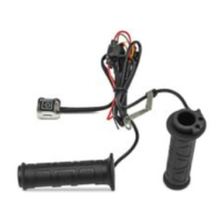
The device features a display that shows the current "MODE" and "VALUE," along with buttons for "MODE SELECT," "(+) VALUE ADJUSTMENT," and "(-) VALUE ADJUSTMENT." These controls allow users to navigate through different modes and adjust numerical values to configure the fuel management system according to specific settings provided in the "Setting Reference." These settings are crucial for tailoring the Fuelpak's operation to the user's specific application and modifications.

Usage Features:

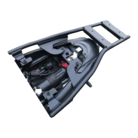
Installation of the Fuelpak is designed to be relatively straightforward, requiring basic tools such as 8 & 10 mm sockets or T-handles and a slotted screwdriver, with an estimated installation time of less than two hours. The unit is mounted under the seat, ensuring it is protected and out of the way.

The installation process involves several key steps:

  1. Preparation: Ensuring the key is in the off position and removing the seat.
  2. Accessing Components: Removing push pins and bolts to access the necessary wiring.
  3. Mounting the Fuelpak: Cleaning the mounting location and securing the Fuelpak with supplied Velcro. The harness is routed between the airbox and subframe, and underneath the subframe cross brace, secured with zip ties, ensuring it avoids the black rubber strip behind the airbox.
  4. TPS Connection: Disconnecting the TPS plug, installing a T-tap to the yellow wire, and connecting the purple wire from the Fuelpak to the T-tap using dielectric grease, then reinstalling the TPS plug.
  5. Ground Wire Connection: Routing the ground wire to the left of the throttle body and in front of the fuel pump, then connecting it to an 8mm bolt on the fuel hose bracket.
  6. Injector Connection: Disconnecting the stock white injector plug and connecting it to the smaller black Fuelpak plug. The larger black Fuelpak plug is then connected to the injector, ensuring a secure "click."
  7. Reinstallation: Reversing the removal process for all components.
  8. Harness Check: Verifying that the Fuelpak harness is not pinched, routed against sharp corners, or touching the exhaust.
  9. Power Pro Module Installation: Installing the White Brothers Power Pro performance module according to its included instructions.

Once installed, configuring the Fuelpak involves a specific sequence of steps:

  1. Accessing the Unit: Removing the clear case cover of the Fuelpak by unscrewing four screws.
  2. Setting Reference: Consulting the Fuelpak Setting Reference for specific values tailored to the user's configuration. If settings are not found, users are directed to fuelpakfi.com or technical support.
  3. Power On: With the run/kill switch in "run" position, turning on the main power with the key (without starting the engine). The Fuelpak display should light up, indicating proper connection.
  4. Throttle Calibration: Pressing the thumb throttle to the full throttle position and releasing before the Fuelpak turns off.
  5. Mode 21 Verification: Starting the engine, then pressing the mode select button twice to navigate to mode 21. Users must verify that the display reads between "0" and "10" with the throttle closed and increases gradually as the throttle is pressed. If not, the engine must be turned off, and the user must return to step 2. This step ensures proper throttle calibration before proceeding.
  6. Value Input: Pressing the mode select button to go to mode 1. Using the (+) or (-) value buttons, users input the correct values as indicated in their Setting Value. After each value is entered, the mode select button is pressed to move to the next mode (up to mode 18). The value increases or decreases by one number with each button press.
  7. Additional Mode Values: Pressing the mode button five times to move to mode 23 and entering any other mode values as required for the application.
  8. Power Off: Turning off the power.
  9. Reassembly: Reinstalling the clear case cover and mounting it, then reinstalling the seat.

After these steps, the device is ready for use.

Maintenance Features:

The manual provides a section for troubleshooting in the event of a malfunction, guiding users through a series of checks:

  1. Connection Verification: Turning off main and handlebar switches and verifying that all connectors are fully seated.
  2. Setting Value Check: Ensuring that the setting values are correct for the specific application.
  3. Throttle Calibration Check: Verifying the throttle calibration as described in step 5 of the "Entering Values" section.
  4. Harness Inspection: Checking the harness for any cuts, scrapes, or abrasions that could compromise its integrity.
  5. Battery and Charging System: Confirming that the battery is fully charged and that the charging system is operating correctly.
  6. Technical Support: If issues persist after these checks, users are advised to call technical support.

The device also comes with a warranty for 90 days from the original retail purchase, covering defects in materials and workmanship. Fuelpak's responsibility is limited to repairing or replacing defective products. The warranty does not cover labor, transportation, consequential damages, or products that have been modified, altered, subjected to adverse conditions (misuse, neglect, accident, improper installation or adjustment, contaminants, corrosion, or faulty repair), or used in applications other than those recommended by Fuelpak. To initiate a warranty claim, consumers must first contact technical support to receive a return authorization number, and the product must be returned with a dated receipt and the authorization number. This structured approach to troubleshooting and warranty claims helps users maintain the functionality of their Fuelpak unit.

Suzuki LTR450 Specifications

General IconGeneral
Rear BrakesHydraulic disc
Starting SystemElectric
Transmission5-speed
Front SuspensionIndependent, double wishbone, coil spring, oil damped
Rear Suspensioncoil spring, oil damped
Front BrakesHydraulic disc

Related product manuals