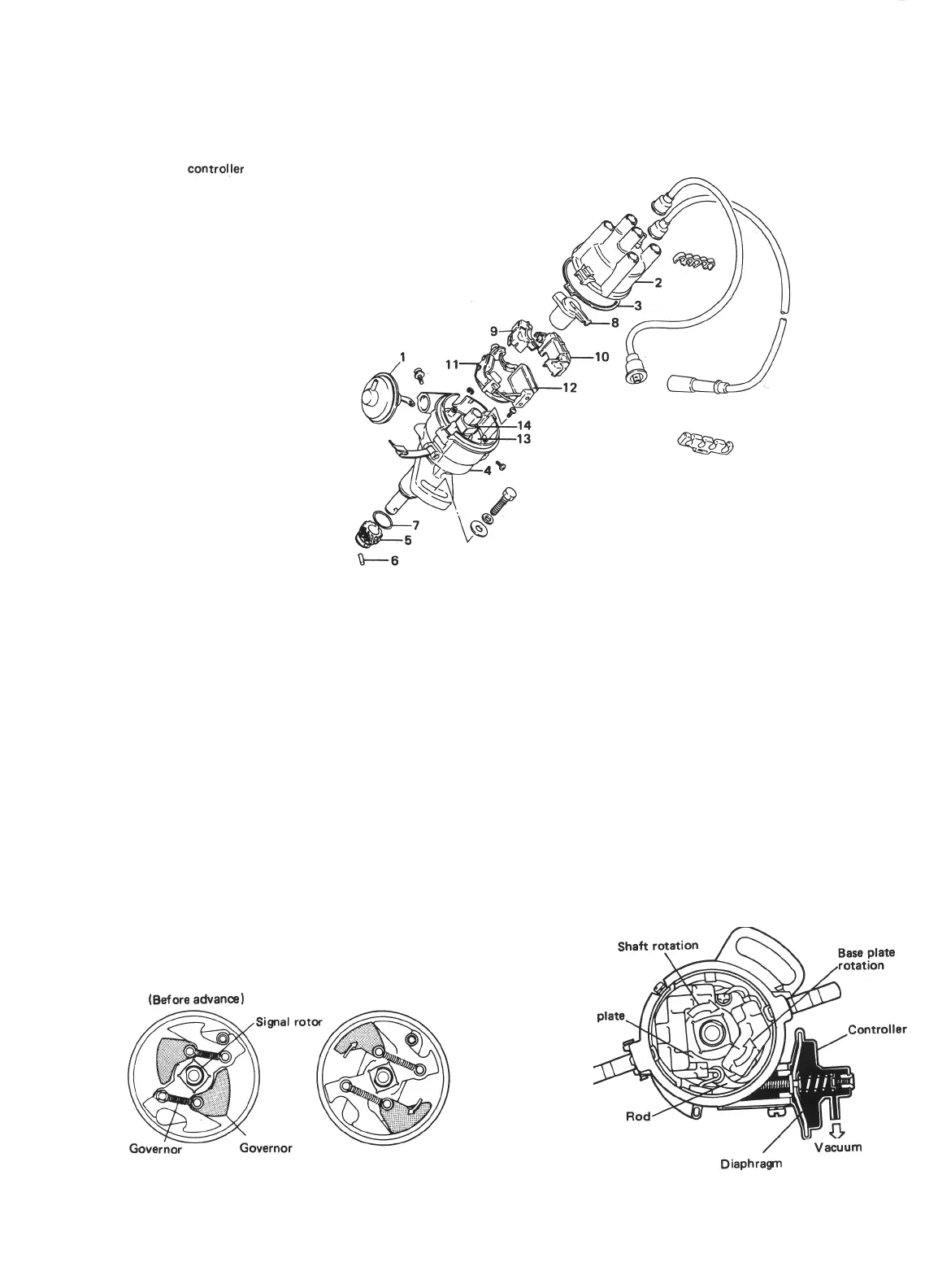
Distributor
1.
Vacuum
ControlJer
2. Distributor cap
3.
Seal
4. Distributor housing
5.
Distributor driven gear
6.
Pin
7.
O-ring
8. Rotor
9.
Signal generator dust cover
10. lgnitor dust cover
11. Signal generator
12.
lgnitor
13. Generator base plate
14.
Signal rotor
Fig. 8-2
[Timing advancer]
[Vacuum advancer]
The distributor shaft, from its driven-gear end to
the rotor-carrying end, is not a single solid piece;
actually this shaft is in two pieces connected
together through the timing advancer. The
advancer is essentially a flyweight mechanism.
Timing advancing action is accomplished by
twisting the top shaft piece relative to the bot-
tom one in the direction of shaft rotation.
The single rotor is mounted on the top piece.
The twisting movement is produced by the
speed-dependent radia I (or spreading) move-
ments of the two flyweights.
In this vacuum-advance mechanism, when the
vacuum in the carburetor gets high, the pressure
acting on the diaphragm overcomes the spring
force in it and the controller rod attached to the
diaphragm is pulled. And the rod so pulled turns
the generator base plate counter to the direction
of the distributor shaft rotation (counterclock-
wise) to advance (quicken) the ignition.
(Before advanca)
(After advance)
Base
C
/
-Vacuum
DiaphragTI
spring
Fig. 8-3
weight
Fig. 8-4
8-3

 Loading...


