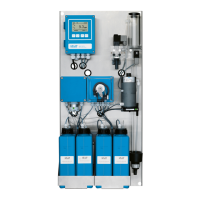
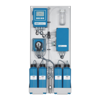
The AMI Silica is a comprehensive monitoring system designed for the automatic and continuous measurement of silica content in water, particularly in power plants or demineralizer plants. It utilizes a colorimetric, molybdosilicate method for silica determination, analyzing molybdate blue at 810 nm. The measurement process involves a series of chemical reactions: silica and ortho-phosphates react at low pH with ammonium molybdate to form yellow silico molybdic acid and phospho molybdic acid. The phospho molybdic acid is then destroyed with oxalic acid, and finally, the silico molybdic acid is reduced with ammonium iron(II) sulfate to form the heteropoly-blue complex. Reagents are added in three steps to the photometer, ensuring precise measurement after the chemical reactions are complete.
Technical Specifications:
- Application Range: Automatic, continuous measurement of silica content in water for power plants or demineralizer plants.
- Silica Measurement Method: Colorimetric, molybdosilicate method at 810 nm.
- Measuring Range: 1 to 5,000 ppb.
- Reproducibility: ±1 ppb or ±5%, whichever is greater.
- Max. PO4 Concentration: <10 ppm.
- Power Supply:
- AC variant: 100–240 VAC (±10%), 50/60 Hz (±5%).
- DC variant: 10–36 VDC.
- Max. Power Consumption: 35 VA.
- Transmitter Housing: Aluminum, IP 66 / NEMA 4X protection degree.
- Ambient Temperature: -10 to +50 °C.
- Storage and Transport Temperature: -30 to +85 °C.
- Humidity: 10–90% relative, non-condensing.
- Display: Backlit LCD, 75 x 45 mm.
- Sample Requirements:
- Flow rate: min. 10 l/h.
- Sample pressure inlet: 0.15–2 bar (2–28 PSI).
- Temperature: up to 50 °C (122 °F).
- Important: Sample must not contain oil, grease, or sand.
- Physical Dimensions:
- Panel: Stainless steel.
- Dimensions: 400 x 850 x 160 mm.
- Screw diameter: 8 mm.
- Weight: 16.0 kg.
- Drain: Tube 15 x 20 mm (1/2”) hose nozzle, pressure-free waste of sufficient capacity.
Usage Features:
The AMI Silica offers several features to enhance its usability and adaptability:
- Grab Sample Measurement: This mode allows for the measurement of samples from remote locations, providing flexibility in monitoring. The measured value of the grab sample is not stored.
- Second Sample Stream Option: The instrument can be equipped with an optional second sample stream module, enabling the monitoring of two distinct sample streams.
- Sample Sequencer Compatibility: For applications requiring measurement of more than two sample streams (up to six), the AMI Silica can be connected to an external Sample Sequencer.
- Signal Outputs: Two programmable signal outputs (0/4–20 mA, max. burden 510 Ω) are available for measured values (scalable linearly or bilinearly) or as continuous control outputs. A third signal output is optional and can be configured as a current source or sink.
- Relay Contacts: Two potential-free contacts are programmable as limit switches for measuring values, controllers, or timers for system cleaning with an automatic hold function. They can be used as normally open or normally closed (max. load: 1 A / 250 VAC).
- Alarm Relay: One potential-free contact serves as an alarm relay, configurable to be open or closed during normal operation, and to switch state on error or loss of power. It provides a summary alarm for programmable alarm values and instrument faults.
- Input: A potential-free contact input allows for freezing the measuring value or interrupting control in automated installations (hold function or remote-off).
- Communication Interfaces (Optional):
- USB Interface for logger data download and firmware upload.
- RS485 with Fieldbus protocols (Modbus or Profibus DP).
- HART interface.
- Safety Features: No data loss after power failure (data saved in non-volatile memory), overvoltage protection for inputs and outputs, and galvanic separation of measuring inputs from signal outputs.
- Measurement Cycle: A complete measurement cycle takes 10 minutes, involving precise reagent dosing by a peristaltic pump, sample intake, mixing with a magnetic stirrer, and photometric analysis. The process includes zero measurement, sequential addition of four reagents, and flushing of the measuring chamber.
- Programming: All parameters for external devices (interface, recorders) and instrument operation (limits, alarms, measuring interval) can be programmed. For multi-channel instruments, the number of channels and channel switching mode can be configured.
Maintenance Features:
Regular maintenance is crucial for the optimal performance of the AMI Silica. The manual provides a detailed schedule and instructions for various tasks:
- Maintenance Schedule:
- Weekly: Check sample supply for dirt and sample flow.
- Monthly: Check reagent level.
- Every 6 months: Exchange reagent pump tube.
- By occurrence (Error Codes):
- E020 (FOME dirty): Cleaning the Photometer.
- E022 (Reagent empty): Refill or replace Reagents.
- E065 (Reagents low): Refill or replace Reagents.
- Stop of Operation for Maintenance: A step-by-step procedure is outlined to safely shut down the instrument, including putting suction lances into demineralized water, starting the fill system, stopping sample flow, waiting for the constant head to empty, and finally shutting off power.
- Refill or Replace Reagents: Instructions are provided for preparing new reagents, including specific chemicals and quantities for Reagent 1 (Ammonium molybdate), Reagent 2 (Sulfuric Acid), Reagent 3 (Oxalic Acid), and Reagent 4 (Ammonium Ferrous Sulfate). Safety precautions, such as reading Material Safety Data Sheets (MSDS) and using personal protective equipment (safety goggles, safety gloves), are emphasized. The manual also details reagent consumption rates based on measuring intervals.
- Verification: An optional "Verification kit for AMI Photometer" allows for checking the instrument's accuracy by comparing measured absorbance with a reference value. The procedure involves stopping sample flow, inserting a verification filter, adjusting for minimal absorbance, and saving the measurement.
- Calibration: Instructions for preparing a standard solution (e.g., 100 ppb from a 100 ppm stock solution) and performing calibration are provided. It is crucial to close the flow regulating valve during calibration if a Sample Sequencer is installed to prevent backflow.
- Cleaning the Flow Cell: Detailed steps for disassembling and cleaning the constant head and acrylic parts of the flow cell are given. Caution is advised against using organic solvents or scrubbing materials on acrylic parts. Replacement of O-rings is recommended during reassembly.
- Cleaning the Photometer: Instructions for cleaning the photometer when an E020 alarm (FOME dirty) is indicated, including closing the flow regulating valve, unscrewing the cover, cleaning with a small brush, and reassembling.
- Cleaning the Solenoid Valve: Steps for disassembling and cleaning the solenoid valve if it is clogged or not switching correctly, including loosening nuts and screws, removing the coil and white plate, and cleaning the base plate and membrane.
- Tube Replacement: The pump tube of the peristaltic pump should be exchanged every 6 months. Instructions include safely opening the pump housing, removing old tubes, connecting new ones, and starting the function.
- Fill or Flush Reagent System: This function is used to fill reagent tubing after refilling containers or to flush the system with demineralized water before a shut-down.
- Longer Stop of Operation: For extended periods of inactivity, specific steps are outlined, such as emptying the measuring cell and relaxing the occlusion frame of the peristaltic pump.
- Replacing Fuses: Instructions for replacing blown fuses, emphasizing the importance of identifying and fixing the cause of the blown fuse, and using original SWAN fuses.
- Troubleshooting: A comprehensive error list with descriptions and corrective actions is provided, covering alarms related to sample parameters, flow, temperature, reagent levels, and hardware failures.