The AMU Powercon is an analytical instrument designed for the measurement of conductivity in high-purity water applications. It can measure either specific (total) conductivity or acid (cation) conductivity. For acid conductivity measurements, a cation exchanger bottle is required. The transmitter is compatible with a two-electrode conductivity sensor that includes an integrated Pt1000 temperature sensor, such as the Swansensor UP-Con1000.
Function Description:
The instrument's primary function is to monitor the total quantity of ions in a solution, which is crucial for controlling water conditions, water purification processes, water hardness, and ensuring the completeness of ion analysis. It offers various temperature compensation curves tailored for different water compositions, including "none," "Coefficient," "Neutral salts," "High-purity water," "Strong acids," "Strong bases," "Ammonia, Eth. am.," and "Morpholine." For cation conductivity measurements (after a cation exchanger), the "strong acids" temperature compensation curve should be used. The displayed conductivity value is always compensated to a standard temperature of 25 °C.
The AMU Powercon features two programmable signal outputs for measured values (scalable as linear, bilinear, or logarithmic) or as continuous control outputs with programmable control parameters. It also includes two potential-free contacts that can be programmed as limit switches for measured values, controllers, or a timer for system cleaning with an automatic hold function. An alarm relay provides a potential-free contact for summary alarm indications based on programmable alarm values and instrument faults. This relay can be configured as normally open (closed during normal operation) or normally closed (open during normal operation). An input for a potential-free contact allows freezing the measuring value or interrupting control in automated installations, programmable as HOLD or OFF functions. Communication interfaces include RS232 for logger downloads and firmware uploads, and optional RS485 with Modbus or Profibus DP protocols.
Important Technical Specifications:
- Electronics Housing: Noryl® resin
- Protection Degree: IP54 (front)
- Ambient Temperature: -10 to +50 °C
- Humidity: 10-90% relative, non-condensing
- Display: Backlit LCD, 75 x 45 mm
- Dimensions: 96 x 96 x 120 mm (DIN 43700)
- Weight: 0.45 kg
- Power Supply: 100-240 VAC (±10%), 50/60 Hz (±5%) or 24 VDC (±15%)
- Power Consumption: Max. 8 VA
- Conductivity Sensor Type: 2-electrode sensor
- Measuring Range (for 0.0415 cm⁻¹ cell constant):
- 0.005–0.999 µS/cm
- 1.00–9.99 µS/cm
- 10.0–99.9 µS/cm
- 100–999 µS/cm
- 1.00–2.99 mS/cm
- 3.0–9.9 mS/cm
- 10–30 mS/cm
- Resolution:
- 0.001 µS/cm
- 0.01 µS/cm
- 0.1 µS/cm
- 1 µS/cm
- 0.01 mS/cm
- 0.1 mS/cm
- 1 mS/cm
- Accuracy: ±1% of measured value ±1 digit
- Sensor Cell Constant: 0.005–10 cm⁻¹
- Temperature Measurement: Pt1000 type sensor (DIN class A)
- Temperature Measuring Range: -30 to +250 °C
- Temperature Resolution: 0.1 °C
- Sample Flow Measurement: With digital SWAN sample flow sensor
- Signal Outputs (Current Loop): 0/4-20 mA, Max. burden 510 Ω
- Relay Contacts (Max. Load): 100 mA/50 V
- Data Storage: Non-volatile memory, over-voltage protection, galvanic separation of measuring inputs and signal outputs.
Swansensor UP-Con1000 Specifications:
- Measuring Range: 0.055–1000 µS/cm
- Continuous Temperature: 100 °C at 6.5 bar
- Max. Temperature: 120 °C at 6.5 bar
- Pressure: Max. 30 bar at 25 °C
- Accuracy (at 25 °C): ±1% or 0.001 µS/cm (whichever is greater)
- Temperature Sensor: Pt1000
- Cell Constant: ~0.04 cm⁻¹
- Mounting: SWAN slot-lock for quick release in suitable flow cells or 3/4" NPT thread.
Usage Features:
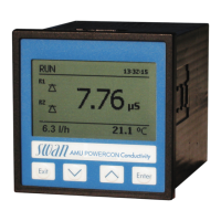
The AMU Powercon is designed for ease of use with a clear display and intuitive key functions. The display shows real-time data including conductivity (R1, R2), sample flow, and sample temperature. It indicates the operating status (RUN, HOLD, OFF, ERROR), time, and relay status with symbols. The software structure is organized into main menus: Messages (1), Diagnostics (2), Maintenance (3), Operation (4), and Installation (5).
- Messages (Menu 1): Provides pending errors and an event history, including time and state of events. No settings can be modified here.
- Diagnostics (Menu 2): Offers user-relevant instrument and sample data, such as identification, sensor details (current value, raw value, cell constant, calibration history), sample information (ID, temperature, flow), I/O state (alarm relay, relays 1/2, input, signal output current), and interface settings. Values in this menu are view-only.
- Maintenance (Menu 3): Used for instrument calibration, simulation of outputs, and setting time/date. This menu is typically for service personnel and can be password-protected.
- Operation (Menu 4): Allows users to modify process-related parameters like sensor filter time constant, hold after calibration, relay contacts (alarm relay, relays 1/2 setpoints, hysteresis, delay), input functions, signal outputs, and logger settings (log interval, clear logger). This menu is usually password-protected for process operators.
- Installation (Menu 5): For initial instrument setup by authorized personnel, defining all instrument parameters, including sensor settings (flow, cell constant, temperature correction, cable length, measuring unit, temperature compensation, quality assurance level), signal outputs (parameter, current loop, function, scaling), relay contacts (alarm relay, sample flow, sample temperature, case temperature, relays 1/2 functions, parameters, setpoints, hysteresis, delay, control parameters), miscellaneous settings (language, set defaults, load firmware, password, sample ID), and interface protocols (Profibus, Modbus RTU, HyperTerminal). This menu is strongly recommended to be password-protected.
Maintenance Features:
The manual outlines a maintenance schedule to ensure optimal performance:
- Monthly: Check sample flow and inspect the cation exchanger resin (if applicable) for color change (red/orange indicates exhaustion).
- As Required: Clean the conductivity sensor and replace the inlet filter of the cation exchanger bottle (if applicable).
- Stopping Operation for Maintenance: Stop sample flow and shut off instrument power.
- Sensor Maintenance:
- Removal: Press down the locking pin, turn the locking screw counterclockwise 180° with a 5 mm Allen key, and remove the sensor.
- Cleaning: For slight contamination, use soapy water and a pipe cleaner. For strong contamination, dip the sensor tip into 5% hydrochloric acid briefly.
- Installation: Ensure the locking mechanism is unlocked, place the sensor into the flow cell aligning marks, and turn the locking screw clockwise 180° to lock.
- Cation Exchanger Replacement:
- Stop sample flow.
- Slightly squeeze the exhausted bottle to prevent water spillage, then unscrew and remove it.
- Fill the new cation exchanger bottle with high-purity water up to the thread.
- Carefully push the new bottle over the inlet filter holder into the bottle holder and screw it in (do not overtighten).
- Open and adjust sample flow.
- Pre-rinse the new resin until stable measuring values are displayed.
- Inlet Filter Replacement:
- Stop sample flow.
- Slightly squeeze the cation exchanger bottle, unscrew, and remove it.
- Unscrew and remove the filter holder from the bottle holder.
- Loosen the four Allen screws with a 1.5 mm Allen key.
- Carefully remove the old inlet filter with a screwdriver.
- Insert a new inlet filter and slightly tighten the Allen screws.
- Screw the cation exchanger bottle into the bottle holder (do not overtighten).
- Calibration: For UP-Con1000 sensors, daily zero measurement is automatic. Calibration is needed if the cell constant is unknown. This involves stopping sample flow, removing and cleaning the sensor, placing it in a calibration solution, waiting for temperature equilibration, and then starting the calibration procedure.
- Longer Stop of Operation: Stop sample flow, slightly squeeze and remove the ion exchanger bottle, close it with a screw cover, store it in a frost-protected room, screw on an empty bottle, and shut off instrument power.
The instrument is equipped with an internal logger that can store approximately 1500 data records (date, time, alarms, measured value, uncompensated measured value, temperature, flow) with programmable log intervals from 1 second to 1 hour. These data can be downloaded to a PC via the RS232 interface. The device also features safety mechanisms such as non-volatile memory for data retention after power failure, over-voltage protection, and galvanic separation of inputs/outputs.