EasyManua.ls Logo

Swegon GOLD RX/HC Series User Manual

Swegon GOLD RX/HC Series
20 pages
To Next Page IconTo Next Page
Page #1 background imageLoading...
Page #1 background image
GB.RXHCF.191011
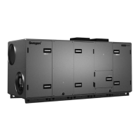
Reversible heat pump GOLD RX/HC
Installation and Maintenance Instructions
Sizes 011-080
The document was originally written in Swedish.
GOLD RX/HC

Questions and Answers:

Swegon GOLD RX/HC Series Specifications

General IconGeneral
BrandSwegon
ModelGOLD RX/HC Series
CategoryHeat Pump
LanguageEnglish

Summary

1. SAFETY INSTRUCTIONS

1.1 Safety Isolating Switch / Main Switch

Details on the location and function of the safety isolating switch.

1.2 Risks and Warnings

General safety warnings and risk areas for refrigerant.

1.3 Electrical Equipment

Information on the location of electrical equipment within the unit.

1.4 Authorization and Personnel

Specifies who is permitted to perform installation and service work.

1.5 Decals and Labels

Information about type designation and serial number labels.

2. OVERVIEW

2.1 General Description

General description of the RX/HC reversible heat pump and its components.

Compressors and System Operation

Details on compressors and the direct-acting system.

Refrigerant and Regulatory Information

Information on refrigerant type, volume, and regulatory compliance.

Quality and Environmental Systems

Information about Swegon's certified quality and environmental systems.

2.2 Basic Function Diagrams

2.2.1 Sizes 011-030

Diagram illustrating the basic functional operation for specific unit sizes.

2.2.2 Size 035

Diagram illustrating the basic functional operation for size 035.

2.2.1 Sizes 040-080

Diagram illustrating the basic functional operation for sizes 040-080.

3. INSTALLATION

3.1 Unloading and Site Transport

Instructions for unloading and transporting the unit to the installation site.

3.2 Unit Arrangement

Guidance on the physical placement and arrangement of the unit.

3.3 Basic Installation Principles

Fundamental principles for installing the GOLD RX/HC unit.

3.3.1 Height Adaptation and Water Trap

Details on adjusting unit height and installing water traps for drainage.

3.3.2 Splitting and Installation of Sections

RX/HC with Full Refrigerant Circuit

Installation instructions for units with a complete refrigerant circuit.

RX/HC with Split Refrigerant Circuit

Installation instructions for units with a split refrigerant circuit.

4. POWER CONNECTION

4.1 Power Connection for Sizes 011-020

Instructions for connecting power supply to units of sizes 011-020.

4.2 Power Connection for Sizes 025-080

Instructions for connecting power supply to units of sizes 025-080.

Electrical Equipment Cubicle - Upper Level

Details on accessing and connecting power in the upper level electrical cubicle.

Electrical Equipment Cubicle - Lower Level

Details on accessing and connecting power in the lower level electrical cubicle.

5. COMMISSIONING AND CALIBRATION

5.1 General Commissioning

General procedures for commissioning and calibration of the unit.

5.2 Phase Sequence Monitor

Description of the phase sequence monitor and its function for compressors.

5.3 Actions for Incorrect Phase Sequence

Steps to take when an incorrect phase sequence is detected.

6. ALARMS

Alarm Information Reference

Reference to the GOLD Manual for Alarms and Information Messages.

7. MAINTENANCE

7.1 Unit Cleaning

Instructions for cleaning the unit, including recommended frequency.

7.2 Refrigerant Handling and Safety

Safety precautions and procedures for handling refrigerant.

7.3 Leakage Tracing and Reporting

Requirements for refrigerant leakage tracing and reporting.

7.4 Authorized Service

Information on who is authorized to perform service on the chiller.

8. TROUBLESHOOTING AND LEAKAGE TRACING

8.1 Troubleshooting Schedule

Table listing common symptoms, possible causes, and actions for troubleshooting.

8.2 Refrigerant Leakage Tracing

Procedures and guidelines for performing refrigerant leakage tracing.

9. DIMENSIONS

9.1 Dimensions for RX/HC 011/012

Dimensional data and drawings for RX/HC unit sizes 011 and 012.

9.2 Dimensions for RX/HC 014/020

Dimensional data and drawings for RX/HC unit sizes 014 and 020.

9.3 Dimensions for RX/HC 025/030

Dimensional data and drawings for RX/HC unit sizes 025 and 030.

9.4 Dimensions for RX/HC 035/040

Dimensional data and drawings for RX/HC unit sizes 035 and 040.

9.5 Dimensions for RX/HC 050/060

Dimensional data and drawings for RX/HC unit sizes 050 and 060.

9.6 Dimensions for RX/HC 070/080

Dimensional data and drawings for RX/HC unit sizes 070 and 080.

10. GENERAL TECHNICAL DATA

Technical Specifications Table

Table of technical specifications including airflow, capacity, and power.

Sizing Guidance

Information and reference for sizing the air handling unit.

11. WIRING DIAGRAM

Wiring Diagram Reference

Reference to a separate document for the unit's wiring diagram.

12. DECLARATION OF CONFORMITY

12.1 Declaration for Sizes 011-020

EC Declaration of Conformity for RX/HC units of sizes 011-020.

12.1 Declaration for Sizes 025-080

EC Declaration of Conformity for RX/HC units of sizes 025-080.

Related product manuals