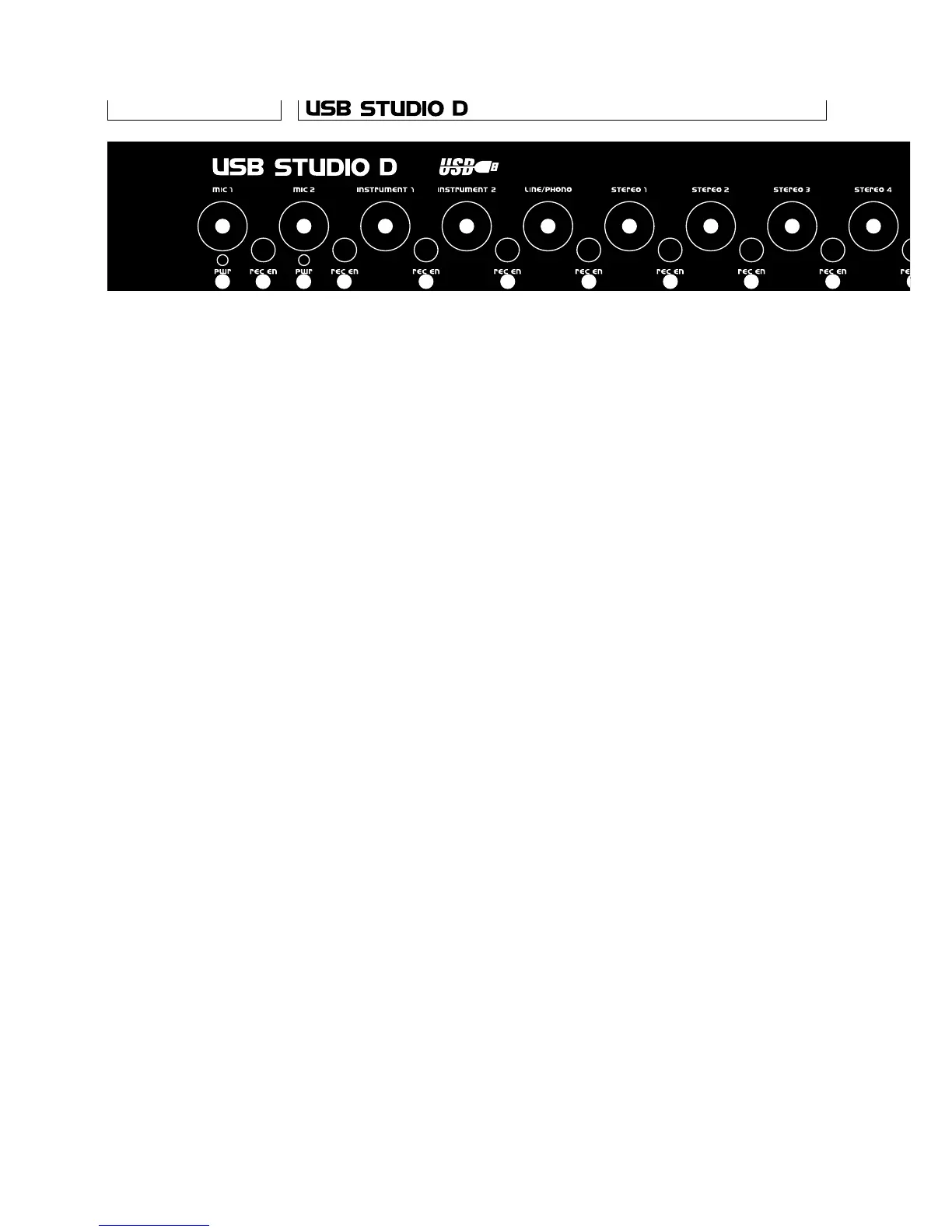
1 Mic 1/2 level pots. Adjust the level of the
respective Mic input. The preamp gain is
automatically adjusted as well, to optimise
SNR and distortion. When turned all the way to the
left, the channel is turned off completely.
2 Mic 1/2 phantom power Leds. When lighted,
show that 48V phantom power is switched on
for the respective input. Some mics could be
damaged by phantom power, so make sure it’s
turned off before connecting one of those.
3 Mic 1/2 record enable switches. When switched
off, the respective input is routed to the monitor
bus. When on (in) the input is added to the rec
bus. When monitoring, both Mic inputs are panned
in the center. When recording, Mic 1 goes to the
left channel and Mic 2 to the right.
4 Instrument 1/2 level pots. As for the Mic inputs,
these also change the preamp gain,
and can turn the channel completely off.
5 Instrument 1/2 record enable switches. When
switched off, the respective input is routed to
the monitor bus. When on (in) the input is added
to the rec bus. When monitoring, both instrument
inputs are panned in the center. When recording,
Instrument 1 goes to the left channel and
Instrument 2 to the right.
6 Line/phono, stereo inputs, digital in level pots.
These are stereo pots adjusting the level of the
respective inpus.
7 Line/phono, stereo inputs, digital in record
enable switches. When switched off, the
respective input is routed to the monitor bus.
When on (in) the input is added to the rec bus.
8 Digital in lock led. When lighted, this shows that
a valid source has been connected to the digital
input, and that the unit has locked to that.
9 Computer level pot. This pot adjusts the level
of the signal coming through the USB interface.
It is always routed to the monitor bus.
Front Panel
6
1
2 3
4
5
6
7
1
2 3
4
5
6
7
6
7
6
7
6
 Loading...