SWS Warning Lights Inc. – 7695 Blackburn Pkwy., Niagara Falls, ON, Canada
Tel: 1-877-357-0222 | Fax: 1-905-357-9122 | Email: sales@warninglightsinc.com
300103_Rev.8
2 | P a g e
Mounting Bracket Installation
1. Drill 2 holes into the mounting surface to mount
the bracket with the drill bit appropriate for
whichever of the mounting methods, shown at
right.
2. Attach the bracket to the desired mounting surface using your chosen method.
3. You may want to avoid attaching the control box to the bracket until after wiring the
connector.
Power Splice Connector
You may need to run your extension cable prior to performing this step.
See image below right (in Fleet Wiring Harness Installation Section) for details.
1. Crimp one end of the supplied butt connectors onto one end of the 15A inline fuse
holder.
2. Crimp the other end of the splice to the positive wire for the product (large 18-16AWG Red Wire)
3. Apply heat to the splice connector to activate the heat-shrink material and seal the connection.
4. Connect the other end of the splice to the Positive connection of your vehicles battery.
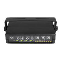
Fleet Wiring Harness Installation
Your product will not use all of the connections available on the connector.
Connect the control box Ground and Positive connections
(#11 & 12) to the vehicles power supply.
The position numbers are for the 12-position connector as
viewed from the rear (screw terminals up).
Optional AUX Product
Positive Wire (10A Max)
Control Box Positive
(Must match product voltage)
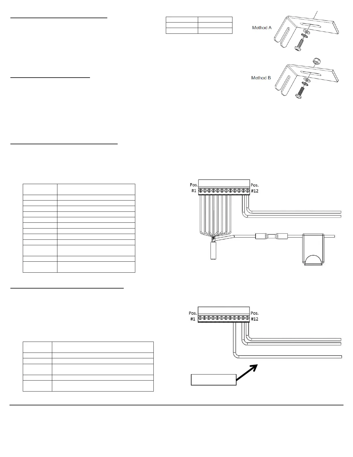
Fleet + Wiring Harness Installation
Your product will not use all of the connections available on the connector.
Connect the control box Ground and Positive connections (#11 & 12) to the vehicles power supply.
The position numbers are for the 12-position connector as
viewed from the rear (screw terminals up).
The product Red (positive) & Black w/ White stripe
(ground) should be connected to the power and ground
separate from the control box.
White LIN Communication (From Product)
Optional AUX Product
Positive Wire (10A Max)
Control Box Positive
(Must match product voltage)
 Loading...