SWS Warning Lights Inc. – 7695 Blackburn Pkwy., Niagara Falls, ON, Canada
Tel: 1-877-357-0222 | Fax: 1-905-357-9122 | Email: sales@warninglightsinc.com
300103_Rev.8
3 | P a g e
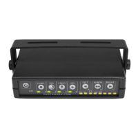
Software Selection
The control box is factory pre-set to 0 if the control box is purchased separately. To
change the function, use the small dial on the back left of the control box (Note the
arrow shape).
* all split arrows and split traffic directors are considered Even numbers, regardless of the number of modules.
Final Installation
Insert automotive fuse into slot in back right of control box if not already present.
Insert 12-position connector into back of control box.
Mount control box to installed mounting bracket using the supplied thumbscrews. Be sure to place the rubber
washers between the control box and the mounting bracket.
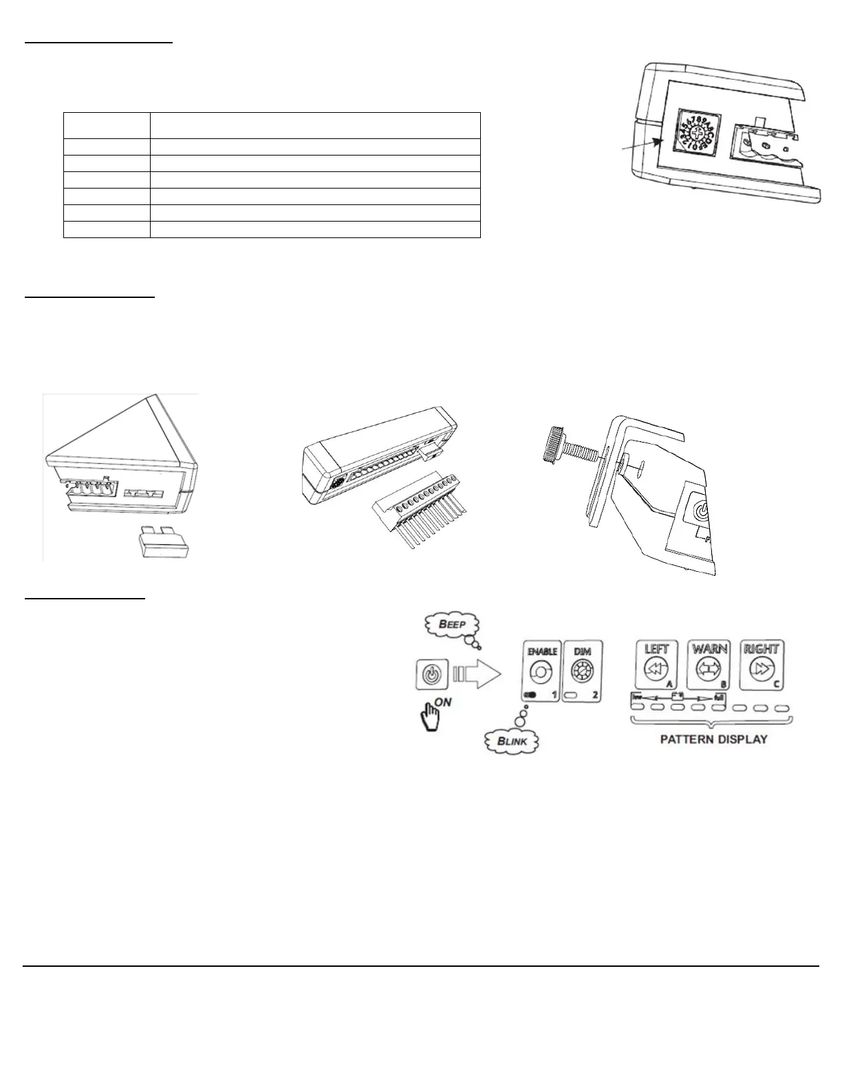
Pattern Control
Pattern control is only activated after the
power button has been pressed.
Upon pressing power ON, the attached
product will enter a warning pattern as
indicated on the pattern display.
By pressing the LEFT, RIGHT, or WARN
buttons, the pattern display will change, BUT
NOT the product.
To complete the change, press the ENABLE
button. The product pattern will then change to match the display and the ENABLE indicator will change from
blinking to solid.
If the ENABLE button is not pressed within 30 seconds, the pattern display will return to the previously enabled
pattern.
There may be more than one variation of each pattern. To select these other variations, repeat the press on
the LEFT, RIGHT, or WARN button until the desired pattern is found. Then press the ENABLE button to
change the pattern of the product.
Traffic Director (Even* Number of Modules)
Traffic Director (Odd Number of Modules)
Traffic Arrow (Even* Number of Modules in Shaft)
Traffic Arrow (Odd Number of Modules in Shaft)
 Loading...