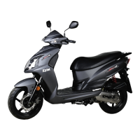
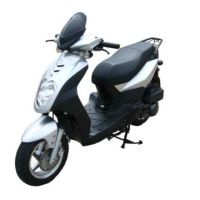
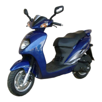
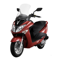
Do you have a question about the Sym Orbit 125 and is the answer not in the manual?
Explains symbols used for service procedures, warnings, and cautions.
Covers critical safety precautions for engine operation, fuel, battery, and brake system handling.
Guidelines on using genuine parts, correct tools, metric system, and component handling.
Lists key technical data for dimensions, weight, engine, performance, tires, and brakes.
Details specific torque values for engine bolts, nuts, and screws during assembly and maintenance.
Lists specific torque values for frame components and standard reference values.
Diagnostic flowchart for engine starting issues, probable causes, and checks.
Troubleshooting flowcharts for engine sluggishness (low power) and potential causes.
Addresses troubleshooting for clutch and driving pulley system issues.
Illustrates key lubrication points on the motorcycle for maintenance.
General precautions and specifications for motorcycle operation and maintenance, including fluid capacities.
Schedule for periodic maintenance tasks, including inspection, cleaning, and replacement intervals.
Details engine oil checks, changes, and strainer cleaning, including oil specifications.
Covers fuel pipe inspection, filter replacement, and safety warnings for gasoline.
Explains removal, inspection, and replacement of the air cleaner element.
Checks and adjustments for throttle valve cable and handle free play.
Guides valve clearance adjustment when the engine is cold.
Adjusts idle speed and emission values using an exhaust analyzer.
Explains checking ignition timing using an ignition light.
Information on recommended spark plug, gap, torque, and confirmation.
Measures compression pressure and identifies low pressure issues.
Covers inspection and replacement of driving belt and clutch pad.
Checks steering handle smoothness and adjusts the top bearing.
Advises on shock absorber condition and checks for front and rear units.
Details brake fluid checks, filling, and air bleeding for the front disc brake.
Measures and adjusts free play for front and rear drum brake levers.
Checks tire pressure, tread depth, wear limits, and tire specifications.
Instructions for battery removal, cable disconnection, cleaning, and installation.
Guides on adjusting the headlight beam height according to regulations.
Emphasizes checking all nuts and bolts for frame security during maintenance.
Illustrates the lubrication system mechanism and oil flow paths.
General information and specifications for engine oil quantity, viscosity, and gear oil.
Lists common lubrication issues like low oil level, leaks, and low pressure.
Details checking engine oil level and performing oil replacement, including torque values.
Explains how to remove, clean, and reinstall the engine oil strainer.
Covers removal, inspection, and re-assembly procedures for the oil pump.
Instructions for inspecting gear oil level and performing gear oil replacement.
Shows an exploded view of fuel system components like the carburetor and fuel tank.
Safety precautions and specifications for the fuel system, emphasizing gasoline hazards.
Diagnostic guide for fuel system problems like poor starting, stalling, and rough idle.
Step-by-step process for removing the carburetor from the motorcycle.
Explains removal and disassembly of the carburetor's vacuum chamber.
Describes removal and installation of the air cut-off valve and its components.
Covers inspection, removal, and installation of the auto by-starter system.
Details disassembly, checking, and cleaning of the carburetor's float chamber and jets.
Guides reinstalling the carburetor and performing necessary adjustments.
Adjusts idle speed and emission values using an exhaust analyzer.
Instructions for removing and installing the fuel unit and the fuel tank.
Details removal, inspection, and replacement of the air cleaner element.
Illustrates engine mounting points and related components with torque values.
Precautions, specifications for oil capacities, and torque values for engine mounting bolts.
Step-by-step guide for safely removing the engine from the motorcycle frame.
Details removing and pressing in engine suspension bushings using specialized tools.
Describes removal and installation of engine suspension frame components.
Guides reinstalling the engine onto the motorcycle frame, including safety notes.
Exploded view of cylinder head, valve train, and associated torque values.
Information and specifications for cylinder head, valve, and camshaft service, including measurement limits.
Addresses top-end issues: rough idle, compression, noise, and white smoke.
Procedure for removing the camshaft, including chain adjuster and timing marks.
Steps for removing the cylinder head, including engine removal and shroud detachment.
Guides cylinder head disassembly, valve spring removal, and component cleaning.
Inspects head flatness, valve spring length, stem diameter, and guide clearance.
Inspects valve seats, measures width, and performs grinding for proper sealing.
Instructions for reassembling cylinder head, lubricating valves, and installing springs.
Details installing the cylinder head, gasket, and camshaft chain plate onto the engine.
Guides assembling camshaft holder, rocker arms, and timing the camshaft.
Explains valve clearance adjustment with a feeler gauge and torque specs.
Illustrates cylinder, piston, rings, and connecting rod assembly with torque values.
Information and specifications for cylinder and piston service, including measurement limits.
Covers issues like low compression, knock, smoking exhaust, and engine overheat.
Details removing the cylinder, including detaching the cylinder head and cam chain.
Explains removing piston rings and the piston pin from the piston.
Guides cleaning piston top, grooves, and installing rings with correct gap placement.
Describes installing the piston and pin into the cylinder, ensuring correct orientation.
Covers cleaning surfaces, installing gasket, and mounting the cylinder head.
Overview of V-belt system maintenance, precautions, specs, torque, and troubleshooting.
Common V-belt system problems: no movement, shuddering, or poor acceleration.
Details removal and installation of the left crankcase cover and kick starter arm.
Explains disassembly, inspection, and reassembly of the kick starter arm.
Covers removal, inspection, and replacement of the driving belt, including width limit.
Details removal, inspection, and installation of the sliding pulley and weight rollers.
Guides disassembly, inspection, and replacement of clutch lining, spring, and bearings.
Specifications for gear oil, lubricants, and torque values for the final drive mechanism.
Lists common issues: starting without movement, noise, and gear oil leaks.
Steps for disassembling the final drive, including rear wheel and clutch removal.
Inspects countershaft, gears, and final driving shaft for wear or damage.
Details replacing bearings in the gear box cover and driving shaft, emphasizing new bearings.
Guides reassembling final drive, installing shafts, gears, cover, and adding gear oil.
Precautions for charging, ignition, and starting systems; emphasizes battery safety.
Explains A.C. generator removal, including oil draining and fan shroud removal.
Details removing right crankcase cover, setting pin, and gasket.
Guides installing right crankcase cover, oil seal, and related components.
Covers installing coil set, pulse generator, and connecting wires.
Describes installing the flywheel, ensuring it's clean and tightened to torque.
Illustrates crankcase and crankshaft assembly with component torque values.
Precautions and specifications for crankcase disassembly, clearances, and torque values.
Addresses engine noise from crankshaft bearings and piston pin wear.
Details crankcase disassembly, bolt removal, and separating the cases.
Inspects crankshaft clearance, run-out, and bearing condition for wear.
Guides crankcase assembly, crankshaft installation, and gasket fitting with torque.
Provides a flowchart for body cover disassembly sequence and precautions.
Details removal and installation of the handle cover and turn signal light connectors.
Explains removal and installation of the front cover, including headlight wire connector.
Guides removal and installation of front under cover, inner box B, and floor panel.
Details removal and installation of front inner box A, including screws and switch cover.
Covers removal and installation of rear body panels, carrier, and fender.
Explains removal and installation of the front center cover and its mounting bolts.
Instructions for removing and installing the luggage box and double seat.
Details removal and installation of the floor panel, including screws and bolts.
Illustrates front disc brake components with torque values.
Shows front drum brake system components and torque values.
Depicts rear drum brake system components and torque values.
Precautions, brake thickness specs, and torque values for brake system components.
Lists common brake issues: soft, hard, uneven brakes, and noise for disc/drum.
Inspects for fluid leaks, hose connections, and checks brake fluid level.
Details brake fluid replacement and bleeding the hydraulic system.
Explains caliper removal, lining replacement, and installation with torque values.
Inspects brake disc for wear, thickness, deformation, and bend with limits.
Details removal, inspection, and assembly of the master cylinder and related parts.
Describes brake drum removal and inspection, including hub ID measurement.
Explains measuring brake lining thickness and replacing worn or contaminated lining.
Covers removal and installation of brake shoes, cam, anchor pin on the brake panel.
Illustrates steering, front wheel, and shock absorber assembly with torque values.
General info, torque values, tools, and troubleshooting for steering and suspension.
Lists common problems: hard steering, wheel wobbling, and suspension issues.
Details removal and installation of the steering handle, including brake connections.
Guides front wheel removal/installation, axle torque, and speedometer cable.
Explains front shock absorber removal/installation, alignment, and torque values.
Describes removal and installation of steering column, bearings, and lubrication.
Illustrates rear wheel, exhaust muffler, and shock absorber assembly with torque values.
General info, wheel wobbling, brake lining specs, and rear component torque values.
Lists issues: rear wheel wobbling, soft shock absorbers, braking noise, poor performance.
Details removal and installation of the exhaust muffler, including connection hardware.
Covers inspection of wheel rim wobbling and rear wheel removal/installation.
Explains rear shock absorber removal/installation, including torque values for mounting bolts.
Illustrates electrical system components: starting, ignition, lighting, fuel unit.
Precautions for charging, ignition, starting systems; battery safety emphasized.
Lists specifications for battery, alternator, ignition components, and starter motor.
Troubleshooting guides for charging, ignition, and starting system failures.
Details current leakage inspection, charging procedures, and voltage/current checks.
Covers ignition circuit, CDI checks, coil testing, and pulse generator resistance.
Explains starter switch inspection, motor removal/installation, and troubleshooting.
Describes removal and installation of the meter assembly, including speedometer cable.
Guides replacing headlight bulbs, adjusting beam, and replacing signal/tail/brake lights.
Covers checking and replacing main switch, continuity tests, and connector checks.
Details fuel unit removal/installation and resistance checks for float arm positions.
| Displacement | 124.6 cc |
|---|---|
| Front Suspension | Telescopic Fork |
| Front Brake | Disc |
| Rear Brake | Drum |
| Wheelbase | 1280 mm |
| Headlamp | Halogen |
| Engine Type | 4-Stroke, Single Cylinder |
| Starting Method | Kick start |
