EasyManua.ls Logo

SymCom MOTORSAVER 460 User Manual

SymCom MOTORSAVER 460
7 pages
To Next Page IconTo Next Page
Page #1 background imageLoading...
Page #1 background image
BE SURE POWER IS DISCONNECTED PRIOR TO INSALLATION!
FOLLOW NATIONAL, STATE, AND LOCAL CODES!
READ THESE INSTRUCTIONS ENTIRELY
BEFORE
INSTALLATION!
INSTALLATION INSTRUCTIONS
FOR SYMCOM’S MOTORSAVER
MODEL 460
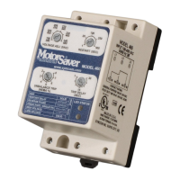
is an auto ranging voltage monitor designed to
protect three-phase motors regardless of size. The MotorSaver
is used on
190-480 VAC, 50 to 60 Hz motors to protect from damage caused by single
phasing, low voltage, high voltage, phase reversal, and voltage unbalance.
CONNECTIONS
1. Mount the MotorSaver
in a convenient location in or near the motor
control panel. If the location is wet or dusty, the MotorSaver
should
be mounted in a NEMA 4 or 12 enclosure. The MotorSaver
can be
mounted to a back panel using two #6 or #8 x 5/8 screws or can be
snapped onto a DIN rail.
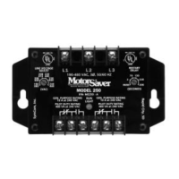
2. Connect L1, L2 and L3 on the MotorSaver’s terminal strip to the LINE SIDE
of the motor starter. (See Figure No. 1).
3. Connect the output relay to the circuitry to be controlled. For motor control,
connect the normally open contact in series with the magnetic coil of the
motor starter as shown in Figure No. 1. For alarm operation, connect the
normally closed contact in series with the control circuit as shown in Figure
No. 2.

Questions and Answers:

SymCom MOTORSAVER 460 Specifications

General IconGeneral
Phase3-phase
Frequency50/60 Hz
EnclosureNEMA 1
Protection FeaturesPhase Loss, Phase Reversal
MountingDIN Rail
Relative Humidity5% to 95% (non-condensing)

Summary

Installation and Connections

Mounting and Enclosure

Mount the device in a convenient location or NEMA 4/12 enclosure using screws or DIN rail.

Line Wiring

Connect L1, L2, and L3 to the LINE SIDE of the motor starter.

Output Wiring

Connect output relay contacts for motor control or alarm operation.

Settings and Adjustments

Line Voltage Adjustment

Adjust the VOLTAGE ADJ. (VAC) dial to the nominal three-phase line voltage.

Restart Delay Adjustment

Set the RESTART (SEC) dial for desired delay before closing output contacts.

Trip Delay Adjustment

Set the TRIP DELAY (SEC) dial for desired tripping delay, excluding phasing faults.

Voltage Unbalance Adjustment

Adjust UNBALANCE TRIP (NEMA%) for desired unbalance trip level.

Power-Up and Indicators

Power-Up Sequence

Turn on power; RUN light blinks during RESTART delay, illuminates upon successful operation.

Diagnostic Indicator Lights

Understand the meaning of RUN, RESTART DELAY, REVERSE PHASE, UNBALANCE/SINGLE PHASE indicator lights.

Troubleshooting

Troubleshooting Symptoms and Solutions

Diagnose issues based on light patterns and symptoms like no power, phase faults, or voltage issues.

Specifications

Dimensions

Related product manuals