EasyManua.ls Logo

Symmons SAFETYMIX VISU-TEMP User Manual

Symmons SAFETYMIX VISU-TEMP
4 pages
To Next Page IconTo Next Page
Page #1 background imageLoading...
Page #1 background image
Single Handle Pressure-Balancing Mixing Valve for Shower or Tub/Shower Application
INSTALLATION, OPERATION & SERVICE INSTRUCTIONS
8"
204mm
4 3/4"
119mm
approx.
35 3/8"
899mm
approx.
42"
1067mm
Ø 1/4”
57mm
NOTE: 2-1/2” (64mm) min.
3” (76mm) max. On 2”x4” con-
struction, use 2-1/2” (64mm)
min. rough-in.
Valve inlets and outlets are
1/2” (13mm) IPS connections.
Symmons valves, shower heads
and hand sprays comply to all
known standards, codes and
specifications: CSA B-125, ANSI
A-112.18.1M, ASSE 1016, EPA ‘92
etc. Symmons shower heads and
hand sprays are equipped with a
2.5 gpm (9.5 L/min) water and
energy saving flow restrictor.
This instruction sheet shows rough-in
dimensions for Models 4-5000VT(X),
1-1000VT(X) and 1-2100VT(X). See
separate drawings enclosed with
numbered models for applicable
rough-in dimensions.
Tools required for installation of this
product are: Phillips screw driver,
tubing cutter, teflon tape, soldering
equipment, adjustable wrench and
channel-lock pliers.
Installation of Shower System
Model 1-1000VT(X) (Figure 2)
Install HOT on left and COLD on right
according to valve markings.
1. Install piping and fittings with valve
body as shown in Figure 2 or 3.
IMPORTANT: Valve rough-in is 2-1/2”
(64mm) min. — 3” (76mm) max. from
CENTERLINE OF SUPPLIES TO FACE
OF FINISH WALL. Install so that surface
indicated on plaster shield on valve
is flush with finish wall as shown in
Figure 1.
2. When finishing tile wall REMOVE
(pull off; don’t turn) ENTIRE PROTEC-
TIVE PLASTER SHIELD and FILL AREA
AROUND VALVE BODY WITH GROUT
OR PLASTER. DO NOT PLASTER OVER
SC-2 CAP OR SERVICE STOPS IF SO
EQUIPPED.
3. Turn on hot and cold supplies, valve
will not operate unless both hot and
cold water are turned on.
4. This valve is equipped with a limit stop
screw to be used to limit valve handle
from being turned to excessively hot
water discharge temperatures. To
adjust, remove dome cover (SC-
13/18), place handle (VT-112) on
stem, open valve to maximum desired
temperature and turn in limit stop
screw (SC-26) until it seats. WARNING:
Failure to adjust the limit stop
screw properly may result in serious
scalding. WARNING: This shower
nish wall face
2
3" 76mm max.
64mm min.
1
2
''
supplies
C
L
plaster shield
4
1
4
''- 4 "
108mm
114mm
1
2
FIGURE 2
Model 1-1000VT(X) Shower System
FIGURE 1
All floor to center dimensions optional. Concealed piping and fittings not furnished by manufacturer.
For California Residents
WARNING: This product contains chemicals known to the State of California to cause cancer, birth defects, or other reproductive harm.
Question and Answer IconNeed help?

Do you have a question about the Symmons SAFETYMIX VISU-TEMP and is the answer not in the manual?

Symmons SAFETYMIX VISU-TEMP Specifications

General IconGeneral
FinishChrome
MaterialBrass
Handle TypeLever
Pressure BalancingYes
ADA CompliantYes
WarrantyLimited Lifetime
Inlet Size1/2 inch
Outlet Size1/2 inch
Temperature AdjustmentYes
Valve TypePressure Balancing
Temperature ControlYes
Installation TypeWall Mount
Inlet Connection TypeIPS
Outlet Connection TypeIPS

Summary

Installation Instructions

Installation of Shower System Model 1-1000VT(X)

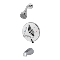
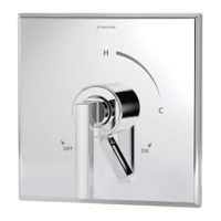
Details on installing the 1-1000VT(X) shower system, including hot/cold connections and rough-in dimensions.

Installation of Tub/Shower System Model 1-2100VT(X)

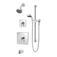
Instructions for installing the 1-2100VT(X) tub/shower system, referencing previous steps and Figure 3.

Fiberglass Wall Installation

Guidance for installing the Visu-Temp in fiberglass or panel walls, emphasizing securing piping to construction.

Parts and Components

Individual Parts

List of individual parts for the Symmons Visu-Temp valve system.

Composite Parts

Catalog of composite parts, including washer and gasket kits for the Visu-Temp.

Repair Units

Available repair units for the Symmons Visu-Temp valve, such as renewable seat kits.

Operation and Maintenance

Operation of Valve

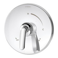
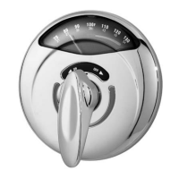
Explanation of how the Visu-Temp valve handle controls temperature and allows for infinite adjustments.

Care and Cleaning

Instructions for cleaning and maintaining the Visu-Temp valve finish to prevent damage.

Service and Troubleshooting

Service

Step-by-step guide for servicing the Symmons Visu-Temp valve, including handle removal and component checks.

Trouble Shooting Chart

A chart detailing common valve problems, their causes, and recommended solutions.

Related product manuals