Figure 2: Recommended smoke alarm protection for single-floor
residence
with more than one sleeping
area:
Figure 5: Recommended smoke-alarm location in rooms with sloped,
gabled
or peaked
ceilings:
ROOM
HORIZONTAL
DISTANCE
FROM
PEAK
3 FEET
(.9M)
LARMS FOR
Where Smoke-Alarms Should NOT Be
Installe
Smoke-alarms shall be installed outside of each separate sleeping area in the
immediate vicinity of the bedrooms and on each additional story of the family
living unit, including basements and excluding crawl spaces and unfinished attics. In
new construction, a smoke-alarm also shall be installed in each sleeping room.”
For better protection, we also require the installation of a smoke-alarm inside every
bedroom in existing construction.
●
In or near areas where combustion particles are normally present such as
kitchens; in garages where there are particles of combustion in vehicle
exhausts; near furnaces, hot water heaters, or gas space heaters. Install
smoke alarms at least 20 feet (6 meters) away from kitchens and other areas
where combustion particles are normally present.
On the ceiling in rooms next to kitchens where there is no transom
between the kitchen and these rooms. Instead, install the smoke alarm on
an inside wall, furthest from the kitchen (See Figure 6). Be sure not to
install smoke alarms within 4" of the ceiling or any corner or more than
6" from the ceiling.
●
●
Install a minimum of two smoke-alarms in any household, no matter how
small it is.
Put a smoke-alarm in the hallway outside of every separate bedroom area.
(See Figure 1.) A minimum of two smoke alarms are required in homes with
two bedroom areas. (See Figure 2.)
Put a smoke-alarm on every level of a multi-level residence (See Figure 3.)
Install basement smoke-alarms on the ceiling at the
bottom
of
the
basement stairwell. (See Figure
3.)
Figure 6: Recommended smoke-alarm locations to avoid air streams
with
combustion
particles:
●
●
AIR INLET
Figure
3:
Recommended smoke-alarm protection
for a multi-level
residence:
AIR RETURN
CORRECT
INCORRECT
BASEMENT
●
In damp or very humid areas, or next to bathrooms with showers. The
moisture in humid air can enter the sensing chamber as water vapor, then
cool and condense into droplets that cause a nuisance alarm. Install smoke-
alarms at least 5 feet (1.5 meters) away from bath-rooms.
In very cold or very hot rooms or areas. Operating temperature of the
smoke alarm is -10°C to 55°C.
In dusty, dirty, or insect-infested areas. Dust and dirt can build up on the
smoke-alarm’s sensing chamber and make it overly sensitive, or can block
openings to the sensing chamber and keep the smoke alarm from sensing
smoke.
ear fresh air inlets or returns or excessively drafty areas. Air conditioners,
heaters, fans, and fresh air intakes and returns can drive smoke away
from smoke-alarms, making the units less effective.
In dead air spaces at the top of a peaked ceiling or wall/ceiling inter sect.
Dead air may prevent smoke from reaching a smoke alarm.
ear fluorescent light fixtures. Install smoke alarms at least 10 feet (3
meters) away from such light fixtures.
SMOKE - ALARMS FOR
MINIMUM PROTECTION
SMOKE - ALARMS FOR MORE
PROTECTION AND
REQUIRED
IN NEW
CONSTRUCTION
Install smoke-alarms on the ceiling as close to the center of the room
as
possible. If this is not practical, install it on the ceiling no closer than
4
inches (10 cm) from any wall or corner. (See Figure
4.)
If wall-mounting is permitted by local and state codes, and
ceiling
mounting is not practical, install smoke alarms on an inside wall
between
4 and 6 inches (10 and 15 cm) from the ceiling. (See Figure
4.)
●
●
●
●
Figure 4: Recommended smoke alarm mounting
locations:
●
NO CLOSER THAN 4" (10 cm)
SIDE WALL
DEAD AIR BEST IN CENTER
SPACE OF CEILING
UNT ON WALL
EAST 4" (10 cm)
FROM CEILING
●
●
NO MORE
AN 6" (15 cm)
FROM CEILING
Installation
Re
uirements
Warning: Electrical Shock Hazard. Turn off power at the main fuse box or
circuit
breaker to the area of smoke alarm installation before beginning
installation
procedures.
●
Mount smoke-alarm to a 4-inch octagonal junction box only. Mount
the
12/24 Volt D.C. power supply to a 4" square junction box 2-1/8"
deep
only. (If necessary, add an extension ring if the selected box does not
have
adequate volume.) The power supply may be mounted remotely from
the
smoke alarm.
All wiring must be performed by a licensed electrician.
Use only the specified wire gauge.
BEST LOCATION
ACCEPTABLE LOCATIO
N
●
Put smoke-alarms at both ends of a bedroom hallway if the hallway is
more than 30 feet (9 meters) long. In addition, large rooms will require
more than a single smoke-alarm if the room is over 900 square feet.
Rooms or areas that do not have smooth ceilings, or which have short,
transom-ty
e walls coming down from the ceiling require additional
smoke-alarms
.
Install second-floor smoke alarms on the ceiling at the top of the first-to-
second floor stairwell. Be sure no door or other obstruction blocks the pat
of smoke to the smoke-alarm.
●
●
●
The smoke-alarm includes a tamper-resist feature that, when
activated,
requires a tool for smoke-alarm removal. The following
smoke-alarm
installation instructions include how to activate this
feature
.
.
●
In rooms with sloped, peaked, or gabled ceilings, install smoke-alarms 3 feet (0.9
meter) measured down on the slant from the highest point of the ceiling. See
Figure 5.
2
I56-2012-00C
FROM
M
AT
BEDROOM
BEDROOM
BEDROOM
GARAGE
LIVING
ROOM
KITCHEN
STOVE
BEDROOM
BATH
KITCHEN
LIVING
ROOM
BEDROOM
KITCHEN
INING
LIVING
ROOM
MINIMUM PROTECTION
ROTECTION AND
ED IN NEW CONSTRUCTION
●
FAMILY
ROOM
- ALA
- A
BEDROOM
BEDROOM
BEDROOM
SMOKE
SMOKE
MORE P
REQUIR
RMS FOR
S
S
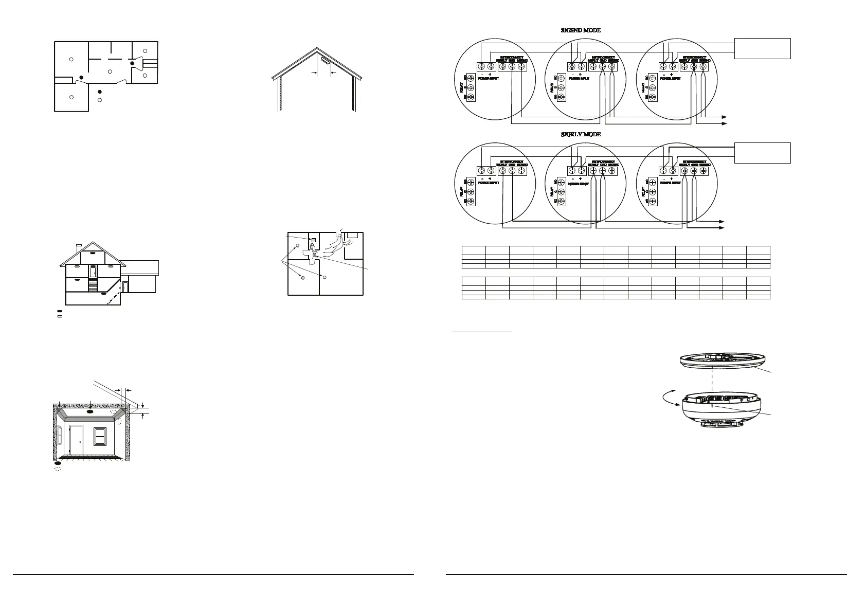
Figure 7:
INTERCONNECT UP TO 24 SMOKE-ALARMS
INTERCONNECT UP TO 24 SMOKE-ALARMS
Maximum power bus length in meters, given number of units (maximum per bus) and wire size (mm
2
).
Supply Voltage = 12VDC
Fo
24
DC supply
oltage, the maximum powe
bus length is 4 times as long as 12
DC supply
oltage.
Maximum interconnect bus length: 2000 meters, 0.75mm
2
or larger cable.
All wiring must conform to local electrical codes.
Figure
8:
Installation Instructions
1.
2.
Turn off power at main service panel.
Using wire connectors, connect power supply output wires to the bus line
wires supplying power to the remote smoke-alarms. (See Figure 7.) Use
color-coded bus wires.
Mount power supply to junction box and cover junction box with a 4"
square box cover, using box mounting screws.
Install a junction box where you plan to install the smoke-alarm. (See type
and size for junction box above.)
Install bus line wires from power supply output to junction box. Use 0.75
to1.5mm wire only. See Figure 7 to determine maximum power bus length
for wire size and number of interconnected smoke-alarms.
Connect color-coded DC power bus wires to power input screw terminals,
located on smoke alarm back. If smoke alarms will be interconnected or
the relay used, see following sections for specific installation instructions.
Remove smoke alarm from mounting bracket by turning the smoke alarm
counterclockwise and pulling the smoke alarm away from the bracket.
Remove small tab on mounting bracket to activate tamper-resist feature, if
desired. (To release a smoke alarm with this feature, push up on locking
tab with screwdriver while turning smoke alarm counterclockwise.)
Install mounting bracket to junction box.
Connect power wires to the smoke alarm(s) as shown in Figure 8. Be sure
to tighten each terminal screw to secure wire in place. Tug wire to be sure
it is connected properly.
Battery installation instruction:
Please open the cover of the battery box on the base with a screwdriver;
Then take the battery button out of the box carefully;
Fasten the battery into the button.
Insert the battery into the box, lock the battery cover with a screwdriver.
Mounting
Bracket
3.
Remove
4.
5.
Install
When Installing:
Align arrows on mounting
bracket 1" to the right of
the nib on the smoke alarm.
Rotate until arrow and
nib line
up
.
The battery box cover will be held up by the spring slice and can not be
closed if the battery is not installed.
Replacement 9VDC batteries can be purchased from the local retail
outlets throughout Australia & New Zealand:
Bunnings, Mitre 10, Tandy and Dick Smith..
6.
7.
●
8.
●
9.
10.
12. Attach the smoke-alarm to mounting bracket by aligning arrows on side of
mounting bracket 1-inch to the right of the nib on the unit. Rotate until the
arrow and nib line up. (See Figure 8).
After installing all smoke-alarms, turn on power at the main service panel.
Check for the green LED to flash once about 40 seconds. This means the
smoke-alarm is receiving power. Check all smoke alarms.
Note: If the LED does not flash, power is not getting to the smoke-alarm.
Check wiring. If LED still does not flash, return the smoke-alarm to
the manufacturer for repair.
Test each smoke-alarm in the system. (See “Testing” below for more
detaile
instructions.
11.
13.
14.
NOTE:
●
●
Only the allowed battery model can be used.
Recommended periodic battery replacement interval: 18 months.
15.
3 I56-2012-00C
12/24VDC SUPPLY
(-)
(+)
Black
12/24VDC SUPPLY
(-)
(+)
WIRE
SIZE
(mm
2
)
1 UNIT 2 UNITS 3 UNITS 4 UNITS 5 UNITS 6 UNITS 7 UNIT 8 UNITS 9 UNITS 10 UNITS 11 UNITS 12 UNITS
1.5
3302 1652 1101
826
660
551
471
413
366
331
301
275
1.0
1633
817
544
408
327
273
233
205
182
163
149
135
0.75
819
411
273
205
163
138
117
103
91
82
75
68
WIRE
SIZE
mm
2
)
13 UNITS 14 UNITS 15 UNITS 16 UNITS 17 UNITS 18 UNITS 19 UNIT 20 UNITS 21 UNITS 22 UNITS 23 UNITS 24 UNITS
1.5
254
236
220
206
194
183
174
165
157
150
144
138
1.0
126
117
109
102
96
91
86
82
78
74
71
68
0.75
63
59
55
51
48
46
43
41
39
37
36
34

 Loading...