1 I56-305-07
PA400*, PS12LO(W), PS12M(W),
PS24LO(W)*, and PS24M(W)*
Electronic Mini-Sounders and
Optional Strobes
*ULC models add suffix “A”; available in 24VDC only
INSTALLATION AND MAINTENANCE INSTRUCTIONS
A Division of Pittway
3825 Ohio Avenue, St. Charles, Illinois 60174
1-800-SENSOR2, FAX: 630-377-6495
General Information
The National Fire Protection Association has published codes,
standards, and recommended practices for the installation and
use of the above appliances. Therefore, the installer must be fa-
miliar with these requirements, with local codes, and any special
requirements of the authority having jurisdiction.
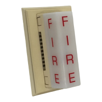
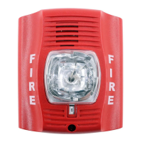
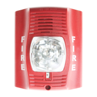
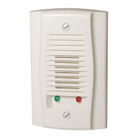
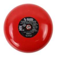
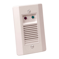
Model PA400
The PA400W (white) and PA400R (red) Piezo Alert electronic
sounder and optional supplementary signal strobes are intended
to be connected to the alarm indicating circuit of a UL-listed 12 or
24 VDC fire alarm control panel. The models PS12 and PS24 op-
tional strobe additions to the PA400 require a 12 VDC or 24 VDC
Specifications
PA400 Sounder
Operating Voltage: 9.6VDC (absolute min.) to 33VDC (absolute max.)
Current Drain: 12 mA at 12 volts
15 mA at 24 volts
Temperature Range: -10
o
C to +60
o
C (14
o
F to 140
o
F)
0°C to 49°C (32°F to 120°F) with strobe added
Sound Output: Greater than 90 dBA measured in anechoic room at 10 feet, 24 volts.
See Figure 1 for other voltages. 82 dBA minimum measured in UL reverbarant room
(75 dBA minimum with strobe)
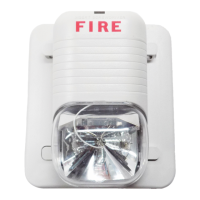
PS12/24 Strobe
MODEL
PS12LO(W) PS12M PS24LO(W) PS24M(W) PS24LOA(W) PS24MA(W)
Panel Voltage 12–17 VDC 12–17 VDC 22.5 - 30 VDC 22.5 - 30 VDC 22.5 - 30 VDC 22.5 - 30 VDC
Max. Current Drain @
Listed Panel Voltage
50 mA 180 mA 25 mA 75 mA 50 mA 180 mA
Min. Light Output @
100% Viewing Angle
(See Fig 2)
1.5 candela 15 candela 1.5 candela 15 candela 1.5 candela 15 candela
86
87
88
89
90
91
92
10 12 14 16 18 2 0 2 2
Voltage
dBA output
F
I
R
E
60% 60%
100%100%
100%
(REF)
7%
60% 60%
7%
Temperature Range: 0°C to 49°C (32°F to 120°F)
Figure 3. 12 volt strobe in-rush current:
1A/div
200
µ
S/div
1A/div
200
µ
S/div
Figure 4. 24 volt strobe in-rush current:
Figure 1: Figure 2:
Under no circumstances can the PS24 voltage exceed 33VDC or be less than 18VDC.
Under no circumstances can the PS12 voltage exceed 18.7VDC or be less than 9.6VDC.
To calculate battery requirements, use current values shown above. However, note that there is an in-rush current associated with
strobe power-up. The information in Figures 3 and 4 is useful when selecting fuse values.
As Figure 3 shows, 12V strobe in-rush current typically peaks at 3A and drops to nominal in 600
µ
S. In a 24V strobe (Figure 4), in-rush
current typically peaks at 7.0A and drops to nominal in 800
µ
S.
panel, respectively and are able to operate from a full-wave recti-
fied, unfiltered supply.
Installation Notes
The wiring must be in compliance with all codes and must not be
of such length or wire size that would cause the appliance to op-
erate outside of its published specifications. The appliances must
also be tested after installation in accordance with the control
panel manufacturer’s test procedure.
NOTE: Do not loop wires under terminal screws. Wires
connecting the device to the panel must be broken at the
device screw terminal in order to maintain electrical
supervision.
Technical Manuals Online! - http://www.tech-man.com