D900-28-00 1 I56-1796-008R
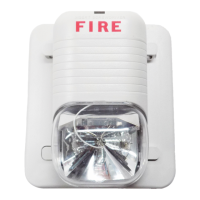
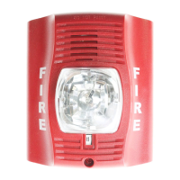
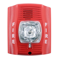
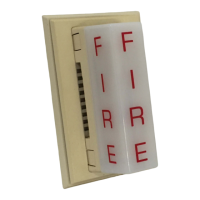
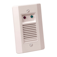
SpectrAlert Selectable Output Strobes,
Horns, and Horn/Strobes
For use with the following models:
Strobes - 12/24 volt: S1224MC, S1224MCW, S1224MCSP, S1224MCSPW, S1224MCP, S1224MCPW
Combo - 12/24 volt: P1224MC, P1224MCW, P1224MCSP, P1224MCSPW, P1224MCP, P1224MCPW
Horns - H12/24, H12/24W
Suffix “W” indicates white housing models. Suffix “SP” indicates “FUEGO” (Spanish word for “FIRE”) lettering on housing.
Suffix “P” indicates plain housing (no lettering).
The Products to which this manual applies may be covered by one or more of the
following U.S. Patent numbers: 5,914,665; 5,850,178; 5,598,139; 6,049,446; 5,593,569, 6,133,843; 6,522,261
INSTALLATION AND MAINTENANCE INSTRUCTIONS
3825 Ohio Avenue, St. Charles, Illinois 60174
1-800-SENSOR2, FAX: 630-377-6495
www.systemsensor.com
General Description
The SpectrAlert series notification appliances are designed
to meet the requirements of most agencies governing these
devices, including: NFPA, ADA, The National Fire Alarm
Code, UL, ULC, FM, CSFM, MEA. Also, check with your
local Authority Having Jurisdiction for other codes or stan-
dards that may apply.
The SpectrAlert series can be installed in systems using 12-
or 24-volt panels having DC or full-wave rectified (FWR)
power supplies. The series can also be installed in systems
requiring synchronization (module MDL or compatible
equivalent required) or systems that do not require syn-
chronization (no module required).
NOTICE: This manual shall be left with the owner/user of
this equipment.
Specifications
Automatic selection for 12 or 24 volt rated operation (DC or Full-Wave Rectified)
Electrical
For Horns, Strobes, and Horn/Strobes
Voltages: Regulated 12 DC/FWR and Regulated 24 DC/FWR
Operational Voltage Ranges: 8-17.5 Volts and 16-33 Volts
Synchronous Applications
with MDL Module: 9-17.5 Volts and 17-33 Volts
NOTE: Horn units will operate on walk tests with on-time durations of .25 sec. or greater.
Flash Rate: 1 flash per second
Operating Temperature: 32° F to 120° F (0° C to 49° C)
Selectable Light Outputs: All candelas are selectable via a manual slide switch.
12/24 Volt Applications: 15 or 15/75 candela
24 Volt Application: 30, 75, 110 candela
15/75 is listed at 15 candela per UL 1971 but will provide 75 candela on axis (straight
ahead). 15, 30, 75, or 110 are rated for that candela.
Sound Output: Sound output levels are established at Underwriters Laboratories in their reverberant
room. Always use the sound output specified as UL Reverberant Room when compar-
ing products.
Listings: UL S5512 (Strobe); UL S4011 (Combo)
Note for Strobes: Do not exceed: 1) 8-17.5 or 16-33 voltage range limit; 2) maximum number of 70
strobe lights when connecting the MDL Sync module with a maximum line imped-
ance of 4 ohms per loop and; 3) maximum line impedance as required by the fire
alarm control manufacturer.
The models
S1224MC, S1224MCW, S1224MCSP, S1224MCSPW, S1224MCP, S1224MCPW, P1224MC, P1224MCW, P1224MCSP, P1224MCSPW, P1224MCP, and
P1224MCPW
incorporate a new patent-pending voltage booster design that has a more consistent flash bulb voltage over the range of candela selections. The
benefit to the customer is a high quality strobe device.
Fire Alarm System Considerations
Temporal and Non-Temporal Coded Signals:
The American National Standards Institute and the National
Fire Alarm Code require that all horns used for building
evacuation installed after July 1, 1996, must produce
Temporal Coded Signals.
Signals other than those used for evacuation purposes do
not have to produce the Temporal Coded Signal. Temporal
coding is accomplished by interrupting a steady sound in
the following manner:
1
/2 Sec.
On
1
/2 Sec.
Off
1
/2 Sec.
On
1
/2 Sec.
Off
1
/2 Sec.
On
1
1
/2 Sec.
Off
Repeats