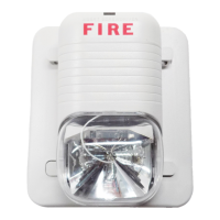
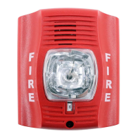
Figure 2: Candela Selections
For strobe candela selection, adjust slide switch located on the rear of the prod-
uct while watching the viewing window on the side of the reflector.
NOTE: SpectrAlert selectable output strobes, set at 15 and 15/75cd, auto-
matically work on both 12V and 24V power supplies.
NOTE: The strobe is not listed for 12V operating voltages when set to 30, 75
or 110 candelas. Use only those settings marked as OK in the chart above.
When using a 12V panel, this device will yield required light output only
in the 15 or 15/75 candela setting.
A0133-00
D900-28-00 2 I56-1796-008R
Permissible Candela Settings:
Candela
Setting
Operating Voltage
12V 24V
15 OK OK
15/75 OK OK
30 OK
75 OK
110 OK
Figure 1A: Current Draw Measurements
NOTE: All ‘S’ and ‘P’ models were only tested at the 8-17.5 and 16-33 Volt-FWR/DC limits. This does not include the
80% low-end or 110% high-end voltage limits.
Model No.
Candela
Setting
FWR Operating
Current–Strobe
(mA RMS)
DC Operating
Current–Strobe
(mA RMS)
FWR Operating
Current–Horn
(mA RMS)
DC Operating
Current–Horn
(mA RMS)
Horn
Audibility
(dBA)12V 24V 12V 24V 12V 24V 12V 24V
S1224MC
Strobe
15 112 64 127 59
15/75 135 74 127 69
30 93 90
75 158 160
110 208 209
P1224MC
Horn/Strobe
15 112 64 127 59 45.7 57.5 44.4 57 75
15/75 135 74 127 69 45.7 57.5 44.4 57 75
30 93 90 57.5 57 75
75 158 160 57.5 57 75
110 208 209 57.5 57 75
H12/24 Horn 45.7 57.5 44.4 57 75
Power Supply Considerations
Panels typically supply DC filtered voltage or FWR (full-
wave rectified) voltage. The system design engineer must
calculate the number of units used in a zone based on the
type of panel supply. Be certain the sum of all the device
currents do not exceed the current capability of the panel.
Calculations are based on using the device current found
in the subsequent charts and must be the current specified
for the type of panel power supply used.
Wire Sizes
The designer must be sure that the last device on the circuit
has sufficient voltage to operate the device within its rated
voltage. When calculating the voltage available to the last
device, it is necessary to consider the voltage drop due to
the resistance of the wire. The thicker the wire, the less the
voltage drop. Generally, for purposes of determining the
wire size necessary for the system, it is best to consider all
of the devices as “lumped” on the end of the supply circuit
(simulates “worst case”).
Typical wire size resistance:
18 AWG solid: Approximately 8 ohms/1,000 ft.
16 AWG solid: Approximately 5 ohms/1,000 ft.
14 AWG solid: Approximately 3 ohms/1,000 ft.
12 AWG solid: Approximately 2 ohms/1,000 ft.
Example: Assume you have 10 devices on a zone and each
requires 50 mA average and 2000 Ft. of 14 AWG wiring
(total length=outgoing +return). The voltage at the end
of the loop is 0.050 amps per device x 10 devices x 3 ohms/
1,000 ft. x 2000 ft =3 volts drop.
Note: If class “A” wiring is installed, the wire length may be
up to 4 times the single wire length in this calculation.
The same number of devices using 12 AWG wire will pro-
duce only 2 volts drop. The same devices using 18 AWG
wire will produce 8 volts drop. Consult your panel manu-
facturer’s specifications, as well as SpectrAlert’s operating
voltage range to determine acceptable voltage drop.
Figure 1B: Selectable Horn Tones
Temporal Low Volume Electromechanical
3000 Hz Interrupted
High Volume Electromechanical
3000 Hz Interrupted
Non-
Temporal
Low Volume Electromechanical
3000 Hz Interrupted
High Volume Electromechanical
3000 Hz Interrupted
 Loading...