D900-08-00 3 I56-732-04
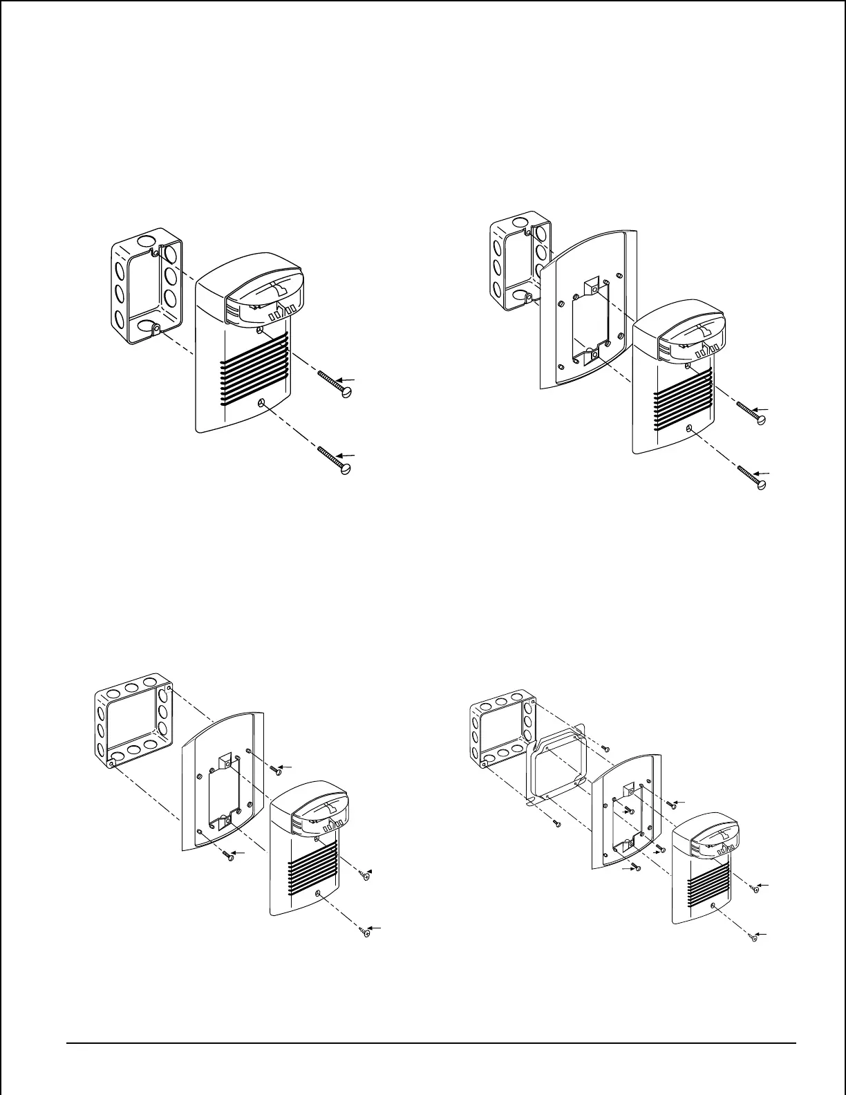
Figure 8. Semi-flush mount with plaster ring or double
gang box:
A
A
Figure 6. Semi-flush mount to single gang box:
A78-2602-00
A
A
Figure 5. Surface mount to single gang box:
Screw types used in Figures 5 – 8 below:
A=#6-32x1-1/2" Phillips Oval Head
B=#8-32x5/8" Slotted Pan Head
C=#6-32x5/8" Slotted Pan Head
D=#8 Phillips Oval Head Sheet Metal
A78-2603-00
Figure 7. Semi-flush mount to 4" box:
1. Screw Semi-Flush Plate to 4" Box with B Screws
2. Complete Field Wiring (See Figure 3)
3. Screw PS12/24ADA to Semi-Flush Plate with D Screws
1) Complete Field Wiring (see Figure 3)
2) Screw PS12/24ADA to Outlet Box with A Screws
1. Screw Semi-Flush Plate to Box with C Screws
2. Complete Field Wiring (See Figure 3)
3. Screw PS12/24ADA to Semi-Flush Plate with D Screws
1. Complete Field Wiring (See Figure 3)
2. Screw PS12/24ADA to Outlet Box with A Screws
A78-2605-00
A78-2604-00
B
B
D
D
Technical Manuals Online! - http://www.tech-man.com