M500-05-00 4 I56-314-14
© System Sensor 1999
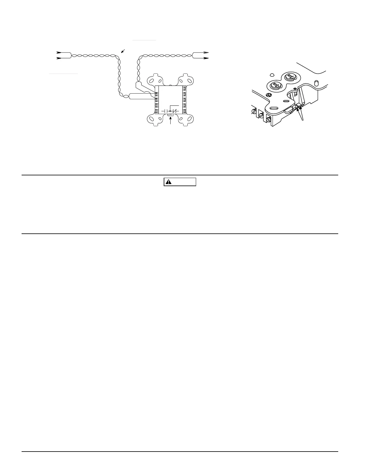
Figure 9. Control module in relay output mode:
WARNING
Control Module switch contacts are shipped in the standby state (open). Contacts may have transferred to the activated state (closed)
during shipping.
The module utilizes a mechanical latching-type relay that can change states due to shock or jarring. The control panel controls this re-
lay with “STANDBY” and “ALARM” control commands. To insure that the switch contacts are in the standby state, control modules
must be made to communicate with the panel before connecting circuits controlled by the module.
1 (–)
2 (+)
MODULE
FROM PANEL OR
(+)
(–)
TO NEXT
(+)
(–)
DEVICE
(+)
(–)
CONTROL
CONNECT MODULES TO LISTED COMPATIBLE
32 VDC MAX.
IS RECOMMENDED
9
8
7
6
5
3
4
RELAY COMMON
NORMALLY CLOSED
FORM "C" RELAY OPERATION WHEN
BOTH TABS J1 AND J2 ARE BROKEN.
J1 & J2
MODULE DOES NOT SUPERVISE CIRCUITS
CONTROLLED BY FORM C CONTACT.
NORMALLY OPEN
RELAY CONTACT RATINGS:
INDUCTIVE: 1 A @ 30 VDC (.6 PF)
RESISTIVE: 2 A @ 30 VDC
PILOT DUTY: .6 A @ 30 VDC (.35 PF)
.3 A @ 110 VDC (.35 PF)
.3 A @ 120 VAC (.35 PF)
M500CH
TWISTED PAIR
CONTROL PANELS ONLY
PREVIOUS DEVICE
COMMUNICATION LINE
BREAK OFF TABS
J1 & J2 TO ENABLE
FORM C OPERATION
ALL WIRING SHOWN IS POWER LIMITED
A78-2286-02
A78-1953-02