Do you have a question about the System Sensor RTS151 and is the answer not in the manual?
Illustrates the connection of the RTS151 to a D4120 4-wire duct smoke detector.
Shows how to wire the RTS151 to a D2-2 wire duct smoke detector, including test coil connections.
Procedure for activating the test function using a magnet on the RTS151.
Describes the delay before the alarm LED lights up when the test function is active.
Instructions for resetting the RTS151 using a small tool to turn off the LED.
Details two methods for wiring the RTS151 to a DNR 2-wire duct smoke detector.
Illustrates the wiring connections between the RTS151 and the DH100ACDC detector.
Provides the wiring scheme for connecting the RTS151 to a DH100 2-wire duct smoke detector.
Shows the specific wiring configuration for the RTS151 with a DH400ACDC detector.
Details the wiring for integrating the RTS151 with Beam1224 and Beam1224S detectors.
The System Sensor RTS151 is an automatic fire detector accessory designed to facilitate the remote testing of fire detectors. This device is intended to be used in conjunction with various System Sensor smoke and beam detectors, allowing for convenient testing and resetting from a remote location. Its primary function is to provide a means to initiate a test sequence and observe alarm indications without direct access to the detector itself, which can be particularly useful for detectors installed in hard-to-reach areas.
The RTS151 serves as a remote interface for fire detection systems. When activated, it sends a signal to the connected smoke or beam detector, initiating a self-test sequence. During this test, the detector simulates an alarm condition. If the detector is functioning correctly, it will enter an alarm state, which is then indicated on the RTS151 by the illumination of its alarm LED. This provides a visual confirmation that the detector is operational and capable of detecting a fire condition.
Beyond testing, the RTS151 also offers a remote reset capability for certain System Sensor detector models. After a test or an actual alarm event, the detector can be reset from the RTS151, returning it to its normal monitoring state. This eliminates the need to physically access the detector to clear an alarm or test condition, streamlining maintenance procedures.
The device is designed for flexibility in installation, capable of being mounted in a single gang box or directly on a wall or ceiling. Its compact dimensions and light weight make it suitable for various installation environments.
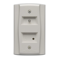
To initiate a test, a user simply places and holds the painted side of the provided M02-04 test magnet to the designated test location on the RTS151. Upon activation, there will be a brief delay, typically up to 40 seconds, depending on the specific detector type being tested, before the alarm indicating LED on the RTS151 illuminates. This delay accounts for the time required for the detector to complete its self-test and signal an alarm. The illumination of the red LED confirms that the connected detector has successfully entered an alarm state, indicating its proper functioning.
For resetting the detector, a small tool, with a maximum diameter of 1/8 inch, is gently inserted into the reset hole on the RTS151 until it stops. This action will turn off the alarm LED and reset the connected detector, returning it to its normal monitoring mode. It's important to note that the RTS151's reset function is compatible only with specific System Sensor detector models, and users should consult the detector's installation instructions for compatibility details.
The RTS151 is compatible with a range of System Sensor detectors, including 4-wire and 2-wire duct smoke detectors (such as D4120, DH100ACDC, DH100, DH400ACDC, and DNR models) and beam smoke detectors (BEAM1224/BEAM1224S). The specific wiring configurations vary depending on the detector model, and detailed wiring diagrams are provided in the manual to guide installers. For certain models, like the D2-2wire duct smoke detector, the RTS151's test coil circuit requires an external UL-listed 24 VDC power supply. Additionally, for these models, an accessory coil (part number DCoil or Coil, depending on the detector series) must be installed separately to enable the remote test station functionality.
In Canadian applications, the RTS151 is intended to be located in the same room as the smoke detector and within 60 feet of the unit, adhering to specific regional installation guidelines.
The RTS151 itself requires minimal maintenance beyond ensuring its proper installation and connection to the detector. The primary maintenance aspect involves its use in testing the connected fire detectors. Regular testing of fire detection systems is crucial for ensuring their reliability and compliance with safety standards. The RTS151 simplifies this process by allowing personnel to perform functional tests from a convenient location, reducing the need for ladders or specialized equipment to access detectors in high or difficult-to-reach areas.
The device's design, with a clear alarm LED and a simple reset mechanism, provides straightforward visual feedback and operational control. Should any issues arise with the RTS151 or the connected detector, the detailed wiring diagrams in the manual serve as a valuable resource for troubleshooting. The manual also emphasizes the importance of consulting the National Fire Protection Association (NFPA) codes, standards, and recommended practices, as well as local codes and the requirements of the local authority having jurisdiction, for the proper installation and use of the product. This ensures that the entire fire detection system, including the RTS151, operates effectively and safely.
The RTS151 is a replacement for the RTS451, indicating an evolution in design and functionality to meet ongoing needs in fire detection system maintenance. Its robust construction and clear operational indicators contribute to its ease of use and long-term reliability within a fire safety system.
| Category | Test Equipment |
|---|---|
| Type | Remote Test Station |
| Operating Temperature | 32°F to 120°F (0°C to 49°C) |
| Humidity | 10% to 93% non-condensing |
| Material | Plastic |
| Device | RTS151 |
| Compatibility | Compatible with System Sensor devices |
| Mounting | Surface Mount |
| Weight | 0.5 lbs |
| Wiring | 18 AWG to 12 AWG |