2 I56-0758-016
©2016 System Sensor. 06-10
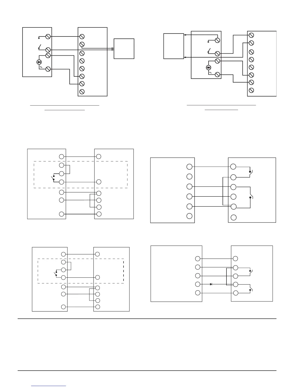
FIGURE 4: WIRING DIAGRAM FOR RTS151KEY(A) TO D2 2-WIRE DUCT SMOKE DETECTOR:
H0612-12
24 VAC (+10%, –15%)
FULL WAVE RECTIFIED,
UNFILTERED POWER
MAY BE USED
RTS151KEY(A)
(OPTIONAL) REMOTE
TEST STATION
MAGNET
TEST
SWITCH
ALARM
LED (RED)
4
5
2
1
(+)
(–)
+ RA
+ RTS
– RA
+ TEST COIL
– TEST COIL
+ IN
+ OUT
–
(–)
(+)
D2
24 VDC
AUX POWER
SUPPLIED
BY USER
(100mA
SUPPLY)
RTS151KEY(A)
(OPTIONAL) REMOTE
TEST STATION
24 VAC (+10%, –15%)
FULL WAVE RECTIFIED,
UNFILTERED POWER
MAY BE USED
MAGNET
TEST
SWITCH
ALARM
LED (RED)
4
5
2
1
(+)
(–)
+ RA
+ RTS
– RA
+ TEST COIL
– TEST COIL
+ IN
+ OUT
–
24 VDC
AUX POWER
SUPPLIED
BY USER
(100mA
SUPPLY)
D2
NOTE: THE USE OF THE RTS151KEY(A) REQUIRES THE INSTALLATION OF
AN ACCESSORY COIL, DCOIL, SOLD SEPARATELY.
METHOD #1 - AUX POWER LOCATED
AT DUCT DETECTOR
METHOD #2 - AUX POWER LOCATED
AT TEST STATION
FIGURE 5. WIRING DIAGRAM FOR RTS151KEY(A) TO DH100ACDC
4-WIRE DUCT SMOKE DETECTOR:
FIGURE 6. WIRING DIAGRAM FOR RTS151KEY(A) TO DH100 2-WIRE
DUCT SMOKE DETECTOR:
NOTE: Terminal 6 of the RTS151KEY(A) is not used when wired to a 2-wire detector.
15
19
14
3
20
2
11
2
6
1
Alarm Signal
Aux. Power +
Sup. N. O.
Sup. COM
Aux. Power “
Reset
Test
(Red LED) Alarm
(Green LED)
Power
DH100ACDCLP
RTS151KEY(A)
5
4
3
*
* Sup. contacts cannot
be used if they are
wired to control panel.
1
2
3
4
5
6
3
4
5
Test +
Test / Reset –
Reset +
Test
Reset
RA +
RA –
V Out +
DH100
RTS151KEY(A)
6
2
1
Alarm
LED
No Connection
H0193-05
H0156-08
THREE-YEAR LIMITED WARRANTY
System Sensor warrants its enclosed product to be free from defects in materials and
workmanship under normal use and service for a period of three years from date of
manufacture. System Sensor makes no other express warranty for the enclosed product.
No agent, representative, dealer, or employee of the Company has the authority to in
-
crease or alter the obligations or limitations of this Warranty. The Company’s obligation
of this Warranty shall be limited to the replacement of any part of the product which is
found to be defective in materials or workmanship under normal use and service during
the three year period commencing with the date of manufacture. After phoning System
Sensor’s toll free number 800-SENSOR2 (736-7672) for a Return Authorization number,
send defective units postage prepaid to: Honeywell, 12220 Rojas Drive, Suite 700, El Paso
TX 79936, USA. Please include a note describing the malfunction and suspected cause
of failure. The Company shall not be obligated to replace units which are found to be
defective because of damage, unreasonable use, modifications, or alterations occurring
after the date of manufacture. In no case shall the Company be liable for any consequen
-
tial or incidental damages for breach of this or any other Warranty, expressed or implied
whatsoever, even if the loss or damage is caused by the Company’s negligence or fault.
Some states do not allow the exclusion or limitation of incidental or consequential dam
-
ages, so the above limitation or exclusion may not apply to you. This Warranty gives you
specific legal rights, and you may also have other rights which vary from state to state.
FIGURE 7. WIRING DIAGRAM FOR RTS151KEY(A) TO DH400ACDC DUCT
SMOKE DETECTOR:
5
7
11
10
6
3
4
2
6
1
Alarm Signal
Aux. Power +
Sup. N. O.
Sup. COM
Aux. Power –
Reset
Test
(Red LED) Alarm
(Green LED)
Power
DH400ACDC
RTS151KEY(A)
5
4
3
*
* Sup. contacts
cannot be used if
they are wired to
control panel.
H0156-09
FIGURE 8. WIRING DIAGRAM FOR RTS151KEY(A) TO BEAM1224/
BEAM1224T SMOKE DETECTOR:
H0585-04
1
2
3
4
5
3
2
1
5
4
RTS151KEY(A)BEAM1224/BEAM1224T
REMOTE ALARM OUT
AUX (–)
TEST INPUT
REMOTE TROUBLE OUTPUT
RESET INPUT
TEST
RESET
T2-3
T3-3
T2-4
T2-2
T2-1
OPTIONAL YELLOW LED
TS151KEY(A) CAN BE USED WITH INTELLIGENT BEAM DETECTOR PRODUCTS.
T INTELLIGENT BEAM DETECTOR MANUAL FOR ADDITIONAL INSTRUCTIONS
(RED LED) ALARM
 Loading...