D690-03-00 2 I56-2769-015R
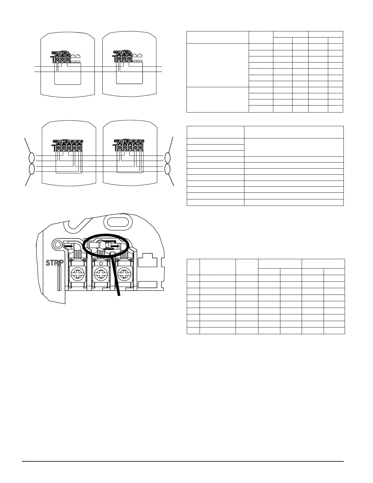
FIGURE 1. WIRING 2-WIRE PRODUCTS:
+
–
+
–
INPUT
FROM
FACP
OR
PRIOR
DEVICE
OUTPUT
TO
NEXT
DEVICE
OR EOL
A0367-01
FIGURE 2. WIRING 4-WIRE PRODUCTS:
+
–
FROM
FACP OR
PRIOR
STROBE
INPUT FROM
+
–
+
–
+
–
TO NEXT
STROBE
OR EOL
OUTPUT TO NEXT
A0366-00
FIGURE 3. SHORTING SPRING:
SHORTING SPRING
A0368-00
NOTE: A shorting spring is provided between terminals 2 and 3 of the mount-
ing plate to enable wiring checks after the system has been wired, but prior
to installation of the final product. This spring will automatically disengage
when the product is installed, to enable supervision of the final system.
CANDELA SELECTION
Adjust the slide switch on the rear of the product to position the desired can-
dela setting in the small window on the front of the unit. All products meet
the light output profiles specified in the appropriate UL Standards. For K series
products used outdoors at low temperatures, listed candela ratings must be re-
duced in accordance with Table 2. Use Table 1 to determine the current draw
for each candela setting. WIRING DIAGRAMS
NOTE: SpectrAlert products set at 15 and 15/75 candela automatically work
on either 12V or 24V power supplies. The products are not listed for 12V op-
erating voltages when set to any other candela settings. For 4-Wire products,
total current draw may be determined by adding current draw for the specific
candela selection in Table 1 with the current draw for the specific horn selec-
tion in Table 3.
TABLE 1. STROBE CURRENT DRAW ( ) FOR S, SC, P4 & PC4 SERIES:
Candela
8–17.5 Volts 16–33 Volts
DC FWR DC FWR
Standard Candela Range
15 123 128 66 71
15/75 142 148 77 81
30 NA NA 94 96
75 NA NA 158 153
95 NA NA 181 176
110 NA NA 202 195
115 NA NA 210 205
High Candela Range 135 NA NA 228 207
150 NA NA 246 220
177 NA NA 281 251
185 NA NA 286 258
TABLE 2. CANDELA DERATING:
Listed Candela
Candela rating at –40°F
(K Series Outdoor Applications Only)
15
Do not use below 32°F15/75
30
75 44
95 70
110 110
115 115
135 135
150 150
177 177
185 185
HORN SELECTION
Turn the rotary switch on the back of the product to the desired setting. For
horn and 4-wire horn/strobe products, the current draw for each setting is
listed in Table 3. For 2-wire horn/strobe products (P2 series), current draws
are listed in Tables 4 and 5. The sound output measurement for each horn
setting is shown in Table 6.
TABLE 3. HORN CURRENT DRAW ( ) FOR H, P4 & PC4 SERIES:
Pos Sound Pattern dA Out
8–17.5 Volts 16–33 Volts
DC FWR DC FWR
1 Temporal High 57 55 69 75
2 Temporal Medium 44 49 58 69
3 Temporal Low 38 44 44 48
4 Non-temporal High 57 56 69 75
5 Non-temporal Medium 42 50 60 69
6 Non-temporal Low 41 44 50 50
7 Coded High 57 55 69 75
8 Coded Medium 44 51 56 69
9 Coded Low 40 46 52 50
NOTE: In positions 7, 8, and 9, temporal coding must be provided by the NAC.
If the NAC voltage is held constant, the horn output will remain constantly on.
Positions 7, 8, and 9 are not available on 2-wire horn/strobe products.
mA
mA
 Loading...