INSTALLATION AND MAINTENANCE INSTRUCTIONS
Selectable Output Strobes, and Horn Strobes
GENERAL DESCRIPTION
The System Sensor series of notification appli-
ances offers a range of strobes and horn/strobes,
for indoor wall and ceiling applications. They are
designed to be used in 24 volt DC or FWR (full
wave rectified) systems. To provide coverage for
the broadest range of applications, products are of-
fered with three selectable candela settings using a
rotary switch on the back of the unit. The strobe
is designed to meet the requirements of UL 1638.
The horn is designed to meet the requirements of
UL 464. High and low volume and temporal 3 or
continuous tone are also selected on the back of the
device using a rotary switch. Not compatible for
use with MDL or MDL3 synchronization modules or
coded power supplies.
For ceiling installations, use ceiling trim ring model
number SYS-CTP for clear lens devices or SYS-CTPR
for red lens devices.
FIRE ALARM SYSTEM CONSIDERATIONS
The National Fire Alarm Code, NFPA 72, requires
that all horns, used for building evacuation pro-
duce temporal coded signals. Signals other than
those used for evacuation purposes do not have
to produce the temporal coded signal. System Sen-
sor recommends spacing notification appliances in
compliance with NFPA 72.
For use with the following models:
SYS-HS, SYS-ST, SYS-HSR, SYS-STR
LOOP DESIGN AND WIRING
The system designer must make sure that the total cur-
rent drawn by the devices on the loop does not exceed
the current capability of the panel supply, and that the
last device on the circuit is operated within its rated
voltage. The current draw information for making
these calculations can be found in the tables within
this manual.
When calculating the voltage available to the last de-
vice, it is necessary to consider the voltage drop due
to the resistance of the wire. The thicker the wire, the
smaller the voltage drop. Wire resistance tables can
be obtained from electrical handbooks. Note that if
Class A wiring is installed, the wire length may be up
to twice as long as it would be for circuits that are not
fault tolerant.
Product Specications
Operating Temperature: 32°F to 120°F (0°C to 49°C)
Humidity Range: 10 to 93% Non-condensing
Strobe Flash Rate: 1 flash per second
Nominal Voltage: Regulated 24V DC/FWR
Operating Voltage Range: 16 to 33V (24V nominal)
Input terminal wire gauge: 14 to 18 AWG
DIMENSIONS FOR PRODUCTS AND ACCESSORIES
NOTICE: This manual shall be left with the owner/user of this equipment.
MOUNTING BOX OPTIONS
2×4, 4×4, single-gang, double-gang, 4˝ octagon,
105mm×150mm, 65mm round, 86mm×86mm,
60mm×60mm.
WALL PRODUCTS LENGTH WIDITH DEPTH
Strobes and Horn/Strobes (including lens)
5.15 in 5 in 1.5 in
131 mm 127 mm 38 mm
SYS-CTP and SYS-CTPR (Ceiling Trim Plate) 6.8 in diameter (173 mm) 1.5 in (38 mm)
Xi’an System Sensor Electronics, Ltd.
28 Tuan Jie South Road, Xi’an Hi-Tech
Development Zone, 710075, Xi’an, China
Tel: (86)29 85387800
SS-120-003 1 I56-3690-000R
I56-3690-000R
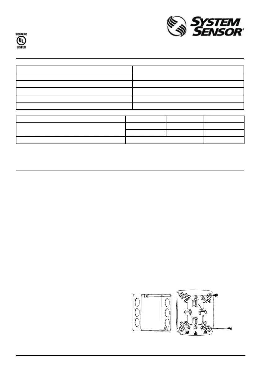
FIGURE 1. MOUNTING PLATE INSTALLATION:
A0433-00
*MOUNTING SCREWS
NOT SUPPLIED