GROOVES
STROBE SELECTION
HORN SELECTION
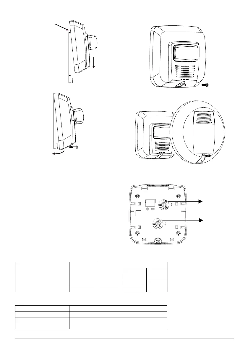
FIGURA 6. HORN AND STROBE SETTINGS:
FIGURA 4A. MOUNTING PLATE ATTACHMENT:
FIGURA 4B. SECURE MOUNTING PLATE:
FIGURA 4C. SECURE PLATE WITH MOUNTING SCREW:
A0440-01
CANDELA AND HORN SELECTION
Adjust the rotary dial on the rear of the product
to position the desired candela setting. Adjust the
other rotary dial for the horn selection. The selec-
tions are high or low volume and continuous or
temporal tone.
A0439-00
A0438-00
A0437-00
A0436-00
FIGURA 5. ROUND TRIM RING FOR CEILING INSTALLATION:
SS-120-003 3 I56-3690-000R
Listed Candela Candela rating with red lens strobe
15 3
75 16
11 5 25
TABLE 2. CANDELA DERATING FOR RED LENS STROBES:
TABLE 1. STROBE CURRENT DRAW ( )
mA
Switch
Position
Candela
16–33 Volts
DC FWR
Standard Candela Range
Position 1 15 37 45
Position 2 75 71 71
Position 3 11 5 89 92