6
Doument in original language
GB
applies).). Installations carried out in accordance with EN 60079-14
are considered to meet the EU installation requirements.
Observation of the guideline 2004/108/EC "electromagnetic
compatibility" only applies when products are directly
connected to the mains supply. The installer/installation owner
is responsible if this product is integrated into an electric
installation or supplemented or driven with other components
(for example controls/control equipment).
The installation must be set up at a safe distance to transmitter
units or protected with suitable screens.
- Before starting installation check for any transport damage, the
distance from the impeller to the fan housing must not be less than
3 mm at any point.
- Ambient temperature and temperature of transported air should
remain within the interval – 20 to + 40°C.
- Fans are intended for continual operation within the given
temperature range.
- The fan can be installed in any direction; unless otherwise
specified.
- Install the fan in the correct air direction (see arrow on fan).
- The fans must be installed so that servicing and maintenance can
be performed easily and safely.
- Check that the fan is firmly fixed and stable and is securely
anchored.
- The fan must be installed so that vibrations cannot be transferred
to the duct system or building structure.
- Disturbing noise can be avoided by installing silencers
(accessory).
- Duct installations must be carried out so that enclosure class IP
20 (mesh width less than 12mm) is fulfilled on the inlet side and IP
10 (mesh width less than 50mm) on the outlet side.
- Parts that assure the IP classification must be correctly designed
with regard to strength and material.
- Rust particles must not be found in the air stream.
- Components that are installed before or after the fan or that are in
the direct air stream may not have unprotected aluminium or steel
surfaces. A surface coating that meets minimum scratch test level 2
according to EN ISO 2409.
- Mains circuit breaker must precede the fans.
- Electrical connection carried out according to wiring diagram on
page 2.
Wiring diagram must be available in the workplace.
- All switched 3-phase fans are supplied from the factory connected
for 400V 3 phase. Does not apply to 230V 3 phase fans.
- If connection is within the potentially explosive environment the
components used must be intended for the relevant Explosive
environment.
- The mains supply for EX fans must be fixed.
- If there is a risk of lightning strikes the installation must be
protected with suitable earthing protection.
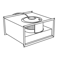
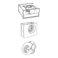
KTEX/DKEX: (see fig. 14 and 15)
- Installation examples only function as a guideline for installation
where dimensioning of suspension devices must be carried out by
the installer and adapted to the prevailing conditions. Fans (3) can
be installed using brackets or suspended mountings (4). If any form
of suspension device or bracket is installed on the fans the distance
to moving parts must not be less than 25 mm. Screw or rivet joints
must be adapted for the purpose and cleaning the fan must be
carried out after completed installation. The hatched areas (5) are
suitable for installation of ducts and any suspension devices. Ducts
(1) should be connected to fans using collars (2) .
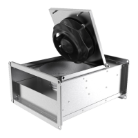
- Supplied with extended connection cable.
- The motors’ connection cable on KTEX is secured with cable ties
in order to guide the cable correctly in relation to the hinge on the
hatch. Attachment must be carried out so that the cable can still be
extended after fixing without the cable insulation being damaged.
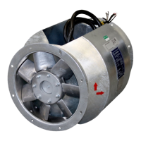
EX 140/180:
- The fans must not be voltage controlled or installed in direct
sunlight.
- The cable end from the fan should be installed so that it is
mechanically protected and suitable for use in the surrounding
environment.
- The installation cable for fan Ex 180-4(440V 3-phase 60Hz)
should be able to withstand min.100°C.
- The installation cable for Ex 140/180 must have a diameter of 6.5
- 12 mm and conducting area of 1.5-2.5mm
2
.
- The junction box is intended for the same environment as the fan.
- For external grounding of the chassis, see image 8.
- Ground cable (b) must be installed between two panel sections
(a).
- Installation holder FKX (2 x ) is available as an accessory. The
holders must be mounted on the motor, see image 7.
Checklist
Always read through the Safety information before
commissioning.
Before starting for the first time, ensure that:
- the ambient temperature, humidity, dirt in the environment and the
air’s corrosive properties have been taken into consideration.
- the impeller does not hit parts of the fan housing (min 3 mm)
- installation and electrical connections are carried out in a
professional manner
- safety equipment is installed.
- any mounting residue and foreign objects are removed from the
impeller and intake area. Loose objects inside the fan may be flung
out!
- protective conductor and external earth conductor are
connected.
- cable gland is sealed?
- PTC resistor and deployment unit are professionally connected
and fully functional.
- connection data corresponds with the data on the rating plate:
maximum voltage +6 %, -10 %, according to IEC 38. Nominal
current/power must not be exceeded at rated voltage.
- static counter pressure may not be lower than the minimum (see
table 1).
- the voltage of controllable fans is permitted to vary between 15 %
and 100 % of nominal voltage with a transformer and between 25
% and 100 % with a thyristor.
- fans are not frequency controlled.
- motor protection functions.
Operation
May only take place when all the safety regulations have been
observed and danger has been ruled out and when the checklist
before commissioning has been completed.
When putting into operation, check:
- that no moving parts are touching the chassis or protection grilles
(min 3 mm).
-that the direction of rotation of the impeller corresponds to the
arrow on the fan.
- that the motor runs smoothly without abnormal noise and that
operation is vibration fee. (Strong vibration because of imbalance,
for example caused by transport damage or incorrect handling can
lead to damage. Check any imbalance as necessary.)
- that all electrical conducting components are grounded through
contact washers,
- that the fans are not controlled by extensive on and off regulation.
- The motors are intended for continuous operation S1. The control
system cannot permit large numbers of switchings.
- A-weighted sound pressure levels above 70dB(A) can occur, see
the product catalogue.
If a fan is stationary for longer than a week in a damp
environment it must be run for two hours every week to
remove any condensation from the motor.
Maintenance, service and repairs
Always read through the safety information before maintenance,
service or repair.
Check that:
- the installation is accessible for cleaning and inspection work.
- no EX atmosphere is present, before switching off the fan.
- that the fan is unpowered and that the current circuit is broken
and secured against restart.