EasyManua.ls Logo

SystemAir HRU 1500 - User Manual

SystemAir HRU 1500
16 pages
Print Icon
To Next Page IconTo Next Page
Loading...
USERS MANUAL
User's Manual
HRU 1500/2500/3500
New Zealand
Question and Answer IconNeed help?

Do you have a question about the SystemAir HRU 1500 and is the answer not in the manual?

Overview

The provided document is a user manual for Systemair HRU 1500/2500/3500 series heat recovery air handling units, designed for installation in centralized mechanical ventilation systems. These units are rated for continuous operation and are suitable for indoor or sheltered use, with an IP54 rating for motors and IP00 for the unit itself (not connected to air ducts). The units are designed to prevent ingress of atmospheric precipitations and direct solar radiation at ambient temperatures from -35 °C up to +50 °C. They are also designed to provide frost protection for drainage and pipelines, and to maintain a minimum medium temperature in water heaters. The corrosion resistance of the unit is class C4 according to ISO 12944.

Function Description

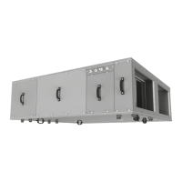
The HRU series units are designed for heat recovery and air handling in ventilation systems. They incorporate various components to ensure efficient air exchange and temperature control. The units can be configured with different automation types, service sides (left or right), motor types (EC – electronically commutated), and additional components such as bypass dampers. They also support various spigot orientations, including suspended mounting and horizontal spigot orientation. The rated air flow is specified in m³/h.

The units are equipped with supply and extract fans, filters, and a heat exchanger. A bypass damper is included for situations where heat recovery is not desired. Control units manage the operation of the system. The design allows for both left-handed and right-handed modifications, enabling flexible installation depending on the duct arrangement. The units are designed to optimize turbulence-induced air pressure losses, connecting the straight air duct section to the spigots on both sides of the unit while mounting. Minimum straight air duct lengths are specified: equal to 1 air duct diameter on the intake side and equal to 3 air duct diameters on the outlet side.

Important Technical Specifications

The HRU series includes three models: HRU 1500, HRU 2500, and HRU 3500. The overall dimensions of the unit vary by model:

  • HRU 1500: A=1340, A1=600, A2=676, A3=713, A4=1350, B=520, B1=1726, B2=1700, B3=9, D=16, D2=16.
  • HRU 2500: A=1610, A1=600, A2=676, A3=713, A4=1350, B=350, B1=1960, B2=1932, B3=9, D=16, D2=16.
  • HRU 3500: A=1350, A1=670, A2=1960, A3=1932, A4=9, B=16, B1=16. (Note: The table for HRU 3500 seems to have some missing or misaligned values for A, A1, A2, A3, A4, B, B1, B2, B3, D, D2. Assuming the provided values are for B, B1, B2, B3, D, D2, and A, A1, A2, A3, A4 are similar to HRU 2500 but with different overall length).

The units are designed for installation in environments with ambient temperatures from -35 °C up to +50 °C. They are rated IP54 for motors and IP00 for the unit.

Additional equipment can be purchased with the units:

  • Control panel: A22, A22 WiFi, A25.
  • Electric heater: HE 600x350-5.1-1 A21, HE 600x350-9.0-3 A21, HE 600x350-12.0-3 A21.
  • DX cooler: CDX 600x350-3.
  • Water cooler: CW 600x350-3.
  • Water heater: HW 600x350-2 A21.
  • Air damper: RRV P600x350.
  • G4 filter: SF 196x384x40 (HRU 1500/2500), SF 253x603x48 (HRU 3500).
  • Air damper actuator: TF 230.
  • Three position ball valve with an electric actuator: Belimo R3020-4-B1+ LR24A-SR (HRU 1500/2500), Belimo R3020-6P3-B1+ LR24A-SR (HRU 3500).
  • Liquid mixing kit for the water heater: USVK 3/4-4 (HRU 1500/2500), USVK 3/4-6 (HRU 3500).
  • Differential pressure switch: DTV 500.
  • Flexible connector: VVG AV 600x350.
  • Silencer: SR 600x350.

The wiring diagram provides details for HRU 1500-3000 models, including connections for power (230V/2A for PK1, PK2, PK3), boost mode input, and heater release output. Control signals include GND, 0-10V, 24V, and connections for CO2 IN, 10V IN, and CONTROL PANEL.

Usage Features

The user manual emphasizes that the installation, maintenance, and operation of the HRU units must be performed by qualified personnel only, properly trained and qualified to install and maintain ventilation equipment. It is crucial to read and understand the user manual before beginning works.

The units are designed for continuous operation. They must not be exposed to any flammable or explosive mixtures, evaporation of chemicals, sticky substances, fibrous materials, coarse dust, soot, or particles or environments favorable for the formation of hazardous substances (toxic substances, dust, pathogenic germs).

The units are equipped with removable service panels for accessing the unit assemblies, including filters, heat exchanger, and bypass damper. These panels are secured with thumbscrews.

Condensate drainage is an important aspect of usage. The unit is equipped with drain spigots for condensate drainage outside the casing. U-traps must be connected to the drain spigots. The dimensions of the U-trap are selected depending on the pressure in the section, shown in a table. It is essential to fill the U-trap with water before starting operation.

The installation diagram for the unit shows recommended minimum clearances for threaded rods, nuts, washers, and vibration absorbing rubber for mounting.

Maintenance Features

Regular inspection, dry cleaning of inner components, check-up, and replacement of air filters in case of filter clogging are required for the unit's operation. Preventive maintenance should be carried out at least once every 6-12 months by a service technician, depending on the operating conditions of the unit. Dust deposits on the inner parts of the unit, especially in the electric heater, may lead to unpleasant odours. Cleaning the unit helps eliminate odours.

Access to filters:

  • Through side service panels: Remove the service panels by unscrewing two thumbscrews securing the retaining plate. The filter elements can then be removed.
  • Through lower service panels: Remove the service panels to access and remove the filter elements.

Access to heat exchanger and bypass damper:

  • Remove the service panel to access the heat exchanger.
  • Disconnect the connector from the bypass damper actuator.
  • Remove the bypass unit, then remove the second heat exchanger.

Storage and Transportation:

  • Store the unit in the manufacturer's original packaging box in a dry closed ventilated premise with temperature range +5...+40 °C and relative humidity up to 70 %.
  • Storage environment must not contain aggressive vapors and chemical mixtures provoking corrosion, insulation, and sealing deformation.
  • Use suitable hoist machinery for handling and storage operations to prevent possible damage to the unit.
  • Follow the handling requirements applicable for the particular type of cargo.
  • The unit can be carried in the original packaging by any mode of transport provided proper protection against precipitation and mechanical damage.
  • The unit must be transported only in the working position.
  • Avoid sharp blows, scratches, or rough handling during loading and unloading.
  • Prior to the initial power-up after transportation at low temperatures, allow the unit to warm up at operating temperature for at least 3-4 hours.

Safety Requirements:

  • All user's manual requirements as well as the provisions of all applicable local and national construction, electrical, and technical norms and standards must be observed when installing and operating the unit.
  • Disconnect the unit from the power supply prior to any connection, servicing, maintenance, and repair operations.
  • Only qualified electricians with a work permit for electrical units up to 1000 V are allowed for installation and maintenance.
  • Check the unit for any visible damage of the impeller, the casing, and the grille before starting installation.
  • While mounting the unit, avoid compression of the casing.
  • Misuse of the unit and any unauthorised modifications are not allowed.
  • Do not expose the device to adverse atmospheric agents (rain, sun, etc.).
  • Transported air must not contain any dust or other solid impurities, sticky substances, or fibrous materials.
  • Do not use the unit in a hazardous or explosive environment containing spirits, gasoline, insecticides, etc.
  • Do not close or block the intake or extract vents.
  • Do not sit on the unit and do not put objects on it.
  • The information in this user's manual must be correct at the time of the document's preparation.
  • The Company reserves the right to modify the technical characteristics, design, or configuration of its products at any time.
  • Never touch the unit with wet or damp hands.
  • Never touch the unit when barefoot.
  • This appliance is not intended for use by persons (including children) with reduced physical, sensory or mental capabilities, or lack of experience and knowledge, unless they have been given supervision or instruction concerning use of the appliance by a person responsible for their safety.
  • Children should be supervised to ensure that they do not play with the appliance.
  • If the supply cord is damaged, it must be replaced by the manufacturer, its service agent, or similarly qualified persons in order to avoid a safety hazard.
  • Ensure that the appliance is switched off from the supply mains before removing the guard.
  • Precautions must be taken to avoid the back-flow of gases into the room from the open flue of gas or other fuel-burning appliances.

The product must be disposed of separately at the end of its service life. Do not dispose of the unit as unsorted domestic waste.

SystemAir HRU 1500 Specifications

General IconGeneral
BrandSystemAir
ModelHRU 1500
CategoryAir Handlers
LanguageEnglish

Related product manuals