24
English
SQ
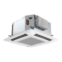
“Hydronic Global Cassette” Fan Coil Units
Legend
Fig.1.
A
- Unit
B
- Frame/Grille assembly
Fig.15.
1 -
Heating: louvre position for correct air
ow
2 -
Cooling: louvre position for correct air
ow
Warning
To close one or two air outlets use the special
kit
Fig.18.
1 - Nut
2 - Wooden frame
3 - Threaded hangers
4 - Washers
5 - Nut
6 - Washers
7 - Threaded hangers
8 - Washers
9 - Nut
10 - Nut
Fig.19.
7 - Threaded hangers
11 - "T" bar (to be removed)
Fig.20.
7 - Threaded hangers
11 - "T" bar (to be removed)
12 - Suspension brackets
18 - Electrical box
Fig.21.
13 - False ceiling
14 - Spirit level
Fig.24.
15 - Frame pre-hooking support
16 - Safety belt
17 - Frame supporting nuts and spacers
Fig.25.
3 - Gasket "A"
4 - Gasket "B"
5 - Air discharge
Fig.26-27.
a - Cold circuit water inlet
b - Cold circuit water outlet
c - Air purge valve
d - Hot circuit water inlet
e - Hot circuit water outlet
Fig.28.
See section “Motorized valve”
Fig.31.
Automatic operation position
f - Valve body
g - Thermo-electric valve head
Fig.32.
Electric heater protections
A - Manual reset thermostat
B - Automatic reset thermostat
Fig.35.-36. Standard.
18 - Electrical box
19 -
Cable holder
20 -
Terminal block
21 -
Electric heater relay
22 -
Capacitor
24 -
Valve cable inlet
25 - Power supply cable
26 - Control cable
Fig.37. Standard with valves
27 - Cold valve cables
28 - Hot valve cables (4 pipes only)
Fig. 38. "IR Control"
18 - Electrical box
19 - Cable holder
20 - Terminal block
21 - Electric heater relay
22 - Capacitor
29 - Transformer
30 - "IR Control" board
Fig. 39. "IR Control" and brushless motor
18 - Electrical box
19 - Cable holder
20 - Terminal block
21 - Electric heater relay
22 - Capacitor
25 - Power supply cable
29 - Transformer
30 - "IR Control" board
31 - EC motor board
Fig.39e. Brush less motor with heaters
Fig.
40e.
Winter operation diagram with fresh air intake
O - Antifreeze thermostat
P - Speed controller
Q - Fresh air fan motor
R - Relay 230V
a= neutral
b= cooling signal 230V
c= heating signal 230V
Fig.44.
Air intake grille
J - Wall
K - Undercut door
L - Wall-tted grille
M - Door-tted grille
Fig.45.
j - Duct connection ange
k - Clip
l - 6 mm neoprene gasket
m - Insulated exible duct
n - Fresh air intake
o - Conditioned air supply to an adjacent room
Fig.47.
Diagram of conditioned air supply to an adjacent room:
one louvre closed
S - Supply air duct to adjacent room
In case of two louvres closed, the fresh air ow towards
the adjacent room is 50% higher compared with only
one louvre closed (with equal static external pressure)
Fig.48.
Filter cleaning
1
2
3
4
5
6
7
 Loading...