24
English
SQ
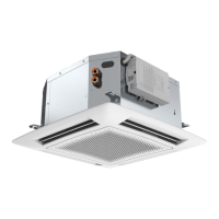
“Hydronic Global Cassette” Fan Coil Units
Legend
Fig.1.
A
- Unit
B
- Frame/Grille assembly
Fig.15.
1 -
Heating: louvre position for correct air
ow
2 -
Cooling: louvre position for correct air
ow
Warning
To close one or two air outlets use the special
kit
Fig.18.
1 - Nut
2 - Wooden frame
3 - Threaded hangers
4 - Washers
5 - Nut
6 - Washers
7 - Threaded hangers
8 - Washers
9 - Nut
10 - Nut
Fig.19.
7 - Threaded hangers
11 - "T" bar (to be removed)
Fig.20.
7 - Threaded hangers
11 - "T" bar (to be removed)
12 - Suspension brackets
18 - Electrical box
Fig.21.
13 - False ceiling
14 - Spirit level
Fig.24.
15 - Frame pre-hooking support
16 - Safety belt
17 - Frame supporting nuts and spacers
Fig.25.
3 - Gasket "A"
4 - Gasket "B"
5 - Air discharge
Fig.26-27.
a - Cold circuit water inlet
b - Cold circuit water outlet
c - Air purge valve
d - Hot circuit water inlet
e - Hot circuit water outlet
Fig.28.
See section “Motorized valve”
Fig.31.
Automatic operation position
f - Valve body
g - Thermo-electric valve head
Fig.32.
Electric heater protections
A - Manual reset thermostat
B - Automatic reset thermostat
Fig.35.-36. Standard.
18 - Electrical box
19 -
Cable holder
20 -
Terminal block
21 -
Electric heater relay
22 -
Capacitor
24 -
Valve cable inlet
25 - Power supply cable
26 - Control cable
Fig.37. Standard with valves
27 - Cold valve cables
28 - Hot valve cables (4 pipes only)
Fig. 38. "IR Control"
18 - Electrical box
19 - Cable holder
20 - Terminal block
21 - Electric heater relay
22 - Capacitor
29 - Transformer
30 - "IR Control" board
Fig. 39. "IR Control" and brushless motor
18 - Electrical box
19 - Cable holder
20 - Terminal block
21 - Electric heater relay
22 - Capacitor
25 - Power supply cable
29 - Transformer
30 - "IR Control" board
31 - EC motor board
Fig.39e. Brush less motor with heaters
Fig.
40e.
Winter operation diagram with fresh air intake
O - Antifreeze thermostat
P - Speed controller
Q - Fresh air fan motor
R - Relay 230V
a= neutral
b= cooling signal 230V
c= heating signal 230V
Fig.44.
Air intake grille
J - Wall
K - Undercut door
L - Wall-tted grille
M - Door-tted grille
Fig.45.
j - Duct connection ange
k - Clip
l - 6 mm neoprene gasket
m - Insulated exible duct
n - Fresh air intake
o - Conditioned air supply to an adjacent room
Fig.47.
Diagram of conditioned air supply to an adjacent room:
one louvre closed
S - Supply air duct to adjacent room
In case of two louvres closed, the fresh air ow towards
the adjacent room is 50% higher compared with only
one louvre closed (with equal static external pressure)
Fig.48.
Filter cleaning
English
25SQ
Unit installation
Read this instruction manual thoroughly before starting
installation.
• This unit complies with the Machinery (2006/42/EC) and
Electromagnetic Compatibility (2014/30/EC) directives.
If Systemair AC controls are NOT used by the installer it is his own
responsibility to check compliance with the following directives:
-Low-voltage (2006/95/EC)
-Electromagnetic compatibility (2014/30/EC)
• This appliance can be used by children aged from 8 years and above and
persons with reduced physical, sensory or mental capabilities or lack
of experience and knowledge if they have been given supervision
or instruction concerning use of the appliance in a safe way and
understand the hazards involved. Children shall not play with the
appliance.
• The installation must be carried out by a qualified installer.
• The unit should be installed according to the national standards
on plants.
• Check that the voltage and frequency of the mains power
supply are as required for the unit to be installed; the available
power source must be adeguate to operate all other appliances
connected to the same line.
• Also ensure that national safety code requirements have been
followed for the main supply circuit.
• Where necessary, use 16 mm I.D. PVC pipe of appropriate length
(not supplied) and with the correct thermal insulation for the
condensate drain extension.
• After installation thoroughly test system operation and explain all
system functions to the owner.
• Use this unit only for factory approved applications: the unit
cannot be used in laundry or steam pressing premises.
WARNING: Disconnect the mains power supply switch before
servicing the system or handling any internal parts of the unit.
• The manufacturer declines any liability for damage resulting from
modifications or errors in the electrical or water connections.
• Failure to observe the installation instructions, or use of the unit
under conditions other than those indicated in Table "Operating
limits" of the unit installation manual, will immediately invalidate
the unit warranty.
• Failure to observe electric safety codes may cause a fire hazard in
the event of short circuits.
• Inspect equipment for damage during transport. In case of damage
file an immediate claim with the shipping company.
• Do not install or use damaged units.
• In case of malfunction turn the unit off, disconnect the mains
power supply and contact a qualified service engineer.
• Maintenance must only be carried out by qualified personnel.
• All of the manufacturing and packaging materials used for this
appliance are biodegradable and recyclable.
• Dispose of the packaging material in accordance with local
requiremements.
Choosing the installation site
Positions to avoid:
• Exposure to direct sunlight.
• Areas close to heat sources.
• On damp walls or in positions that may be exposed to water
hazard.
• Where curtains or furniture may obstruct free air circulation.
Recommendations:
• Choose an area free from obstructions which may cause uneven
air distribution and/or return.
• Consider using an area where installation is easy.
• Choose a position that allows for the clearances required.
• Look for a position in the room which ensures the best possible
air distribution.
• Install unit in a position where condensate can easily be piped to
an appropriate drain.
... any obstruction of the unit air intake or supply grilles (See g. 3).
... exposure to oil vapours (See g. 4).
... installation in areas with high frequency waves (See g. 5).
... ascending sections of condensate drain piping.
These may only be used near the unit with a maximum height
difference of 200 mm from the top of the unit (See g. 6).
... horizontal sections or curves of condensate drain piping with less
than 2% slope (See g. 7).
... exposure to direct sunshine, when the unit is operating in the
cooling mode; always use shutters or shades.
... positions too close to heating sources which may damage the
unit (See g. 8).
... connecting condensate piping to sewage system drain without
appropriate trap.
Trap height must be calculated according to the unit discharge
head in order to allow sufcient and continuous water evacuation
(See g. 9-10).
... only partial insulation of the piping.
Non-level installation which will cause condensate dripping (See
g. 11).
... attening pipes or condensate pipes (See g. 12-13).
... slack on electrical connections (See g. 14).
General Information
Warnings: avoid
 Loading...