EasyManua.ls Logo

SystemAir SYSCROLL AIR CO/HP 40-75

SystemAir SYSCROLL AIR CO/HP 40-75
64 pages
To Next Page IconTo Next Page
Loading...
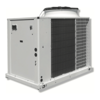
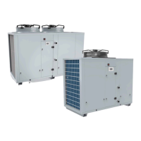
Air Cooled Water Chillers and Heat Pumps
Refroidisseurs de liquide à condensation par air et pompes à chaleur air-eau
Luftgekühlte Flüssigkeitskühler und Wärmepumpen
Refrigeratori d’Acqua e Pompe di Calore Raffreddati ad Aria
Enfriadores de Agua y Bomba de Calor Condensadas con Aire
Installation and maintenance manual
Manuel d'installation et de maintenance
Installations- und Wartungshandbuch
Manuale di installazione e di manutenzione
Manual de instalación y de mantenimiento
SYSCROLL AIR CO/HP 40-75
SYSCROLL AIR RE 40-75
ISO 9001:2008 certified management system
40
75 kW
40
75 kW
Español
ItalianoDeutsch
FrançaisEnglish
Part number / Code / Code / Codice / Código: 364354/F
Supersedes / Annule et remplace / Annulliert und ersetzt / Annulla e sostituisce /
Anula y sustituye:
342597/E
Notified Body / Organisme Notifié / Benannte Zertifizierungsstelle /
Organismo Notificato / Organismo Notificado N°. 1115

Questions and Answers:

SystemAir SYSCROLL AIR CO/HP 40-75 Specifications

General IconGeneral
RefrigerantR410A
Cooling capacity40-75 kW
CompressorScroll
Power Supply400V/3Ph/50Hz
TypeAir-cooled chiller
Heating Capacity45-80 kW
Sound Power Level68 dB(A)

Summary

Foreword

1.1 Introduction

Overview of unit's purpose and manual's scope.

1.2 Warranty

Conditions for warranty validity and voiding factors.

1.3 Emergency stop Normal stop

Procedure for stopping and restarting the unit.

1.4 An introduction to the manual

Explanation of manual conventions and symbols.

Safety

2.1 Foreword

General safety compliance with directives and precautions.

2.2 Definitions

Defines key roles: Owner, Installer, Operator, Engineer.

2.3 Access to the unit

Rules for accessing the unit area and personnel safety.

2.4 General precautions

General safety rules for operators and installers.

2.5 Precautions against residual risks

Safety measures for control, mechanical, and electrical hazards.

2.6 Precautions during maintenance operations

Specific safety steps before and during maintenance.

2.7 Safety labels

Identification of refrigerant, unit labels, and safety warnings.

2.8 Safety regulations

Safety data and precautions for R410A refrigerant.

Transport, Handling and Storage

3.1 Inspection

Procedures for unit inspection upon receipt and damage reporting.

3.2 Handling

Instructions for lifting, moving, and protecting the unit.

3.3 Anchoring

Guidance on securing the unit to foundations.

3.4 Storage

Precautions for storing the unit before installation.

Installation

4.1 Installation site

Criteria for selecting unit location and ensuring adequate space.

4.2 External Water Circuit

Requirements and components for the external water circuit.

4.3 Water connections

Details for connecting plant water lines to the unit.

4.4 Defrost water drainage

Installation requirements for HP units during defrost cycles.

4.5 Water buffer tank

Information and components of the optional water buffer tank.

4.6 Power supply

Electrical connection requirements, safety measures, and sizing.

4.7 Electrical connections

Detailed instructions for making electrical connections to the unit.

Start-up

5.1 Preliminary check

Essential checks before unit start-up.

5.2 Start-up

Step-by-step sequence for safely starting the unit.

5.3 Checking the operation

Procedures for verifying unit performance post start-up.

5.4 Delivery to the customer

Guidance for training end-users on unit operation.

SyScroll Air COHP Control

6.1 Control of SyScroll Air COHP units

Overview of the microprocessor control system.

6.2 Keypad functions

Description of keypad buttons and their functions.

6.3 Folder structure

Explanation of the controller's menu structure.

6.4 Menu structure

Detailed breakdown of controller menu options.

6.5 Alarm list

Comprehensive list of unit alarms, codes, and statuses.

SyScroll Air RE Control

7.1 Control system

Overview of the microprocessor control system for RE units.

Keyboard & Display Terminal

Description of the control terminal, LCD, and LEDs.

7.2 Display

Details on the LCD display interface and information display.

7.3 Keyboard

Explanation of keyboard button functions for operation.

7.4 Alarms

Lists and describes system alarms with codes.

Product Description

8.1 General Information

Overview of unit features, capabilities, and construction.

Body and Frame

Description of the unit's base and frame construction materials.

Compressors

Details on compressor type, protection, and operation.

Evaporators

Description of the evaporator component and its specifications.

Condensing coils

Description of the condenser coils and their construction.

Condenser Fans

Description of the condenser fan type and motor.

Refrigerating Circuits

Overview of refrigerant circuit components and safety devices.

Control Supply Panel

Description of the electrical control panel and its components.

8.2 Accessories

List of available optional accessories for the unit.

8.3 Refrigerant flow diagram - SyScroll Air CO 40 to 75 - R410 A

Diagram illustrating the refrigerant circuit for CO units.

Refrigerant flow diagram - SyScroll Air HP 40 to 75 - R410 A

Diagram illustrating the refrigerant circuit for HP units.

Refrigerant flow diagram - SyScroll Air RE 40 to 75 - R410 A

Diagram illustrating the refrigerant circuit for RE units.

Technical Data

9.1 Hydraulic features

Graphs showing evaporator and desuperheater water pressure drops.

Optional pump available static pressure

Graph detailing available static pressure for optional pumps.

Optional pump power input

Graph showing power input for optional pumps.

9.2 Physical data - CO BLN

Physical specifications for SyScroll Air CO BLN models.

Physical data - CO SLN

Physical specifications for SyScroll Air CO SLN models.

Physical data - CO HTHPF

Physical specifications for SyScroll Air CO HT/HPF models.

Physical data - HP BLN

Physical specifications for SyScroll Air HP BLN models.

Physical data - HP SLN

Physical specifications for SyScroll Air HP SLN models.

Physical data - RE BLN

Physical specifications for SyScroll Air RE BLN models.

Physical data - RE HTHPF

Physical specifications for SyScroll Air RE HT/HPF models.

Physical data - RE SLN

Physical specifications for SyScroll Air RE SLN models.

9.3 Electrical data

Tables detailing electrical specifications for different unit series.

Compressor electrical data

Specific electrical data for the unit's compressors.

Fan electrical data

Specific electrical data for the unit's fans.

Pump electrical data

Specific electrical data for the unit's pumps.

9.4 Position of shock absorbers and weight distribution on supports

Table showing weight distribution and mounting coordinates.

9.5 Dimensional Drawings - COHP 40-50

Dimensional drawings for SyScroll Air CO/HP 40-50 units.

Dimensional Drawings - COHP 60-75

Dimensional drawings for SyScroll Air CO/HP 60-75 units.

Dimensional Drawings - RE 40-50

Dimensional drawings for SyScroll Air RE 40-50 units.

Dimensional Drawings - RE 60-75

Dimensional drawings for SyScroll Air RE 60-75 units.

9.6 Space Requirements

Diagram illustrating required clearances for unit installation.

Maintenance

10.1 General requirements

General guidelines and responsibilities for unit maintenance.

10.2 Planned maintenance

Schedule and procedures for planned maintenance tasks.

10.3 Refrigerant charge

Procedures for safely charging and checking refrigerant levels.

10.4 Compressor

Information on compressor oil, replacement, and handling.

10.5 Condenser

Instructions for cleaning and maintaining the condenser coils.

10.6 Fans

Description of the condenser fan components.

10.7 Dehydrating filter

Procedures for checking and maintaining the dehydrating filter.

10.8 Sight glass

How to inspect refrigerant flow and humidity using the sight glass.

10.9 Thermostatic expansion valve

Checking and regulating the thermostatic expansion valve.

10.10 Evaporator

Maintenance procedures for the evaporator, including cleaning.

Troubleshooting

Troubleshooting Table

Lists unit anomalies, their causes, and corrective operations.

Spare Parts

12.1 Spare part list

Recommended list of spare parts for the first two years of operation.

12.2 Oil for compressors

Information about the type of lubricating oil used for compressors.

12.3 Wiring diagrams

Indicates where wiring diagrams are located within the unit.

Dismantling, Demolition and Scrapping

13.1 Generalities

General procedures for safely dismantling and disposing of unit components.

Related product manuals