24
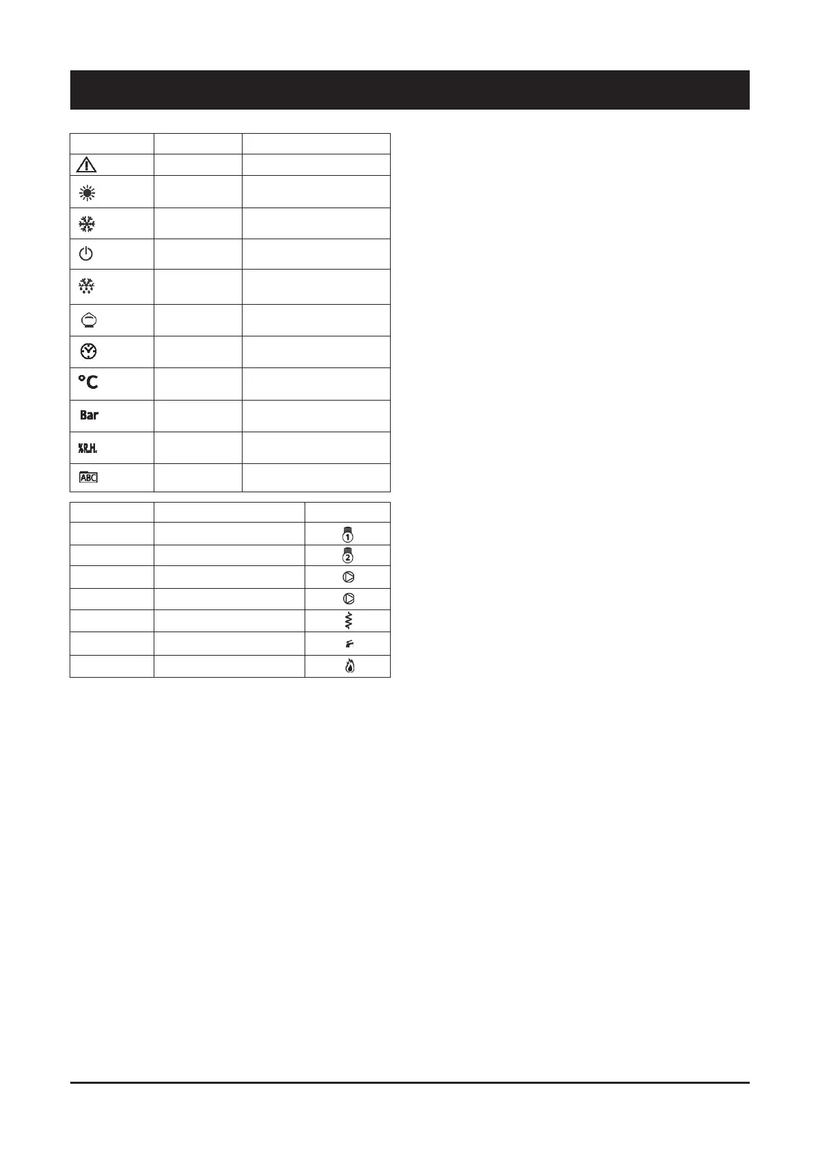
6 - SyScroll Air CO/HP Control
ICON / COLOR
LED N°*
STEADY ICON
DESCRIPTION
BLINKING ICON
ICON
- Alarm ON
First capacity step
Second capacity step
Primary circuit pump
Source circuit pump
Electrical heater
Sanitary hot water valve / pump
Boiler
/ RED
1
2
3
4
5
6
7
/ GREEN
/ GREEN
/ GREEN
/ GREEN
/ GREEN
/ RED
/ RED
/ RED
/ RED
/ RED
- Mode: HEATING
- Current HR
- Time slots activ.
- Mode: COOLING
/
/
/
- Mode: STAND-BY
- Configurable
Not used
Menu surf
- Alarm QUIT
- Antifreeze+Heat pump ON
- Heating mode by remote
- HR setting
- Time slots programming
- Cooling mode by remote
/
/
/
- Stand-by mode by remote
- Configurable
Not used
/
6.3 Folder structure
Folder structure is composed of totally four menus
1) Main display¤used to set what to display without acting on any
key
– Ai¤analogue input (temperature, pressure)
– rtC¤room time clock
– SetP¤standard set-point
– SetR¤corrected set-point (according to climatic correction,
etc.)
2) Operating mode¤used to set operating mode
– StbY¤stand-by
– HEAT¤heating
– COOL¤cooling
– AS¤sanitary hot water
3) Status¤used to show resources values
– Ai (AIL/AIE/Air)¤analogue inputs (main board / expansion
board / remote terminal)
– di (diL/diE)¤digital inputs (main board / expansion board)
– AO (AOL/AOE) ¤ analogue outputs (main board/expansion
board)
– CL (HOUr/dAtE/YEAr)¤clock
– AL (Er00¤Er98)¤alarms
– SP¤standard set-point
– Sr ¤ corrected set-point (according to climatic correction,
etc.)
4) Program¤define parameters, functions, password and to display
alarm log
6.4 Menu structure
“Program” menu is composed of totally four folders
1) Parameters¤change unit parameters
2) Functions¤manual operations (switch ON / switch OFF, alarm
quit, historic alarm delete, multi function key use)
3) Password¤define visibility levels for parameters/folders
4) Alarm log¤display alarm log
Parameter folder gives access to following sub-folders
– CL/CE/Cr/CF¤configure device I/O (L¤local; E¤expansion; r
¤remote; F¤serial)
DQDORJXH LQSXWV W\SH RI SUREH UDQJH GLIIHUHQWLDO ORJLF
function)
GLJLWDOLQSXWVORJLFIXQFWLRQ
GLJLWDORXWSXWVORJLFIXQFWLRQ
DQDORJXHRXWSXWVUDQJH
VHULDOFRQILJXUDWLRQFRPPXQLFDWLRQSDUDPHWHUV
– TR¤define thermoregulation parameters
VHWSRLQWPD[PLQK\VWHUHVLV
W\SHSURSRUWLRQDOGLIIHUHQWLDO
SUREHVHOHFWLRQ
– ST¤define operating status
FRROLQJRQO\
KHDWLQJRQO\
VFRROLQJDQGKHDWLQJ
FKDQJHRYHU
– CP¤configure compressor parameters (type/number/timing)
– PI¤define primary circuit / parameters / functions
RSHUDWLQJPRGHGLVDEOHDOZD\V2121LIFRPSUHVVRU21
GLJLWDODQDORJXHFRQWURO
DQWLVWLFNLQJ
DQWLIUHH]H
– BR ¤ control the parameters for an additional step for heating
and for sanitary hot water integration (boiler)
RSHUDWLQJPRGHGLVDEOHGLIIHUHQWLDO¤ fixed or in function of
outdoor air temperature)
VHWSRLQWK\VWHUHVLV
– DS¤define set-point offset (dynamic set-point) depending on
DQDORJXHLQSXW«9«9«9«P$
RXWGRRUDLUWHPSHUDWXUH
URRPWHPSHUDWXUH
– AD¤simulate an electronic inertial accumulator, acting on set-
point and hysteresis (adaptive function), by confronting minimum
/ effective ON-OFF time
– AS¤define sanitary hot water management parameters
RSHUDWLQJPRGHGLVDEOHVDQLWDU\KRWZDWHUYDOYHUHVLVWDQFH
/ pump)
VHWSRLQWK\VWHUHVLV
DQWLOHJLRQHOODIXQFWLRQ
– HP¤define heat pump block management parameters
RXWGRRUDLUWHPSHUDWXUH
WKHUPRUHJXODWLRQWHPSHUDWXUH
GLJLWDOLQSXW
– PL ¤ define capacity limitation to protect the unit (high/low T,
high/low P)
– TE ¤ define time slots management (different operating daily
profiles)
– AL¤define alarms management (automatic / manual reset, by-
pass time, sampling)
 Loading...