52
1355
1395
1685
1580
C
D
4 x Ø22
1100
23105423
1750
517
112 1121527
987
987
1100
P2
P1
P3
P4
50 1000 50
25
I
L
H
F
G
61275
23105423
112 1527 112
P3
P4
P2
P1 4 x Ø10
Q R
241
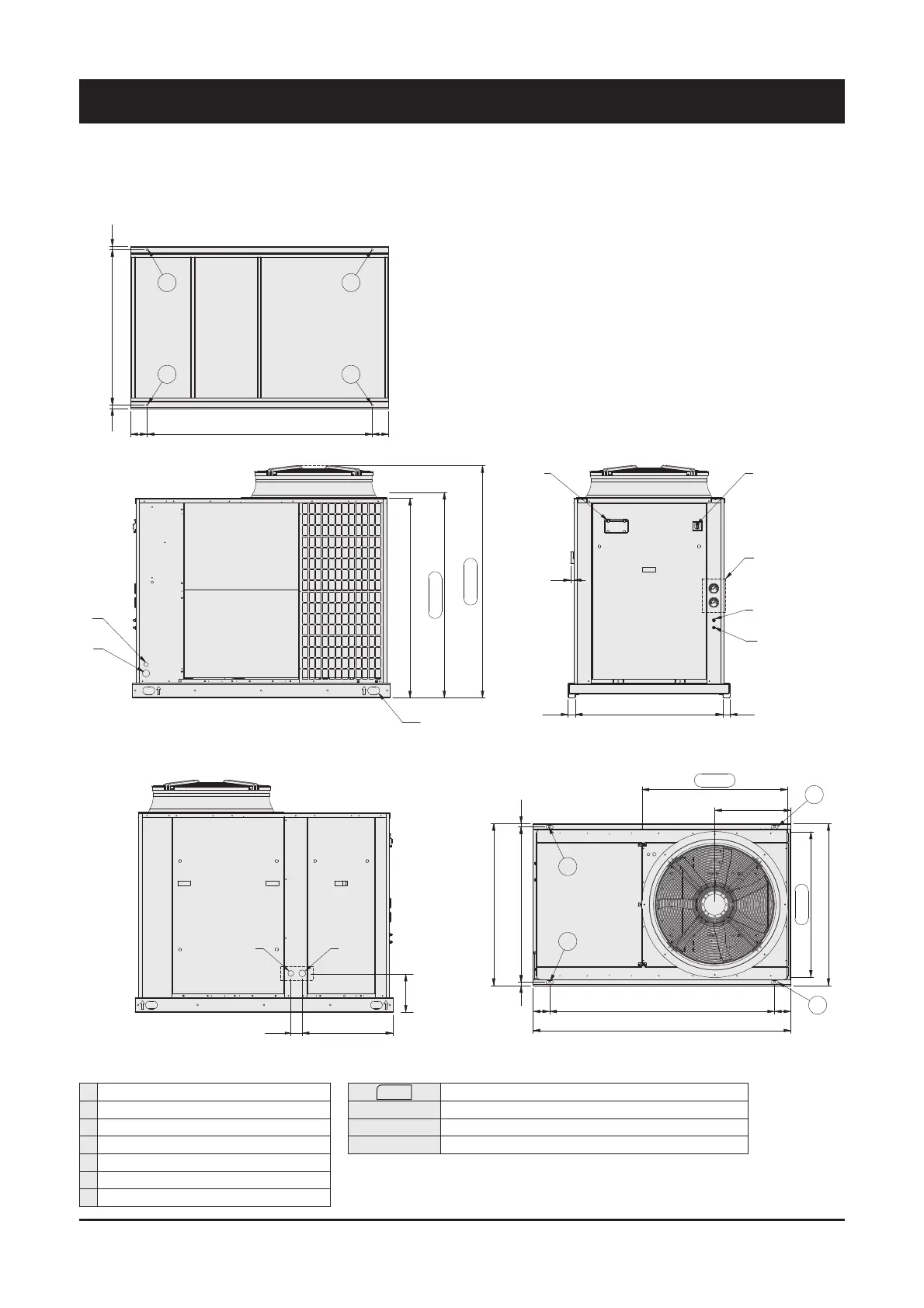
Front view
Bottom view
Side view Top view
C Electrical auxiliary lines
D Electrical power supply
F High pressure tap
G Low pressure tap
H Gauge kit (accessory)
I Main switch
L Control keypad/display
XXX Only for HT/HPF fan model
P1, P2, P3, P4 AVM position
Q Liquid line Ø 5/8"
R Suction line Ø 1 3/8"
9 - Technical Data
Dimensional Drawings - Units SyScroll Air RE 40 to 50 - R410A
Dimensions in mm.
 Loading...