188
A
E
B
N
M
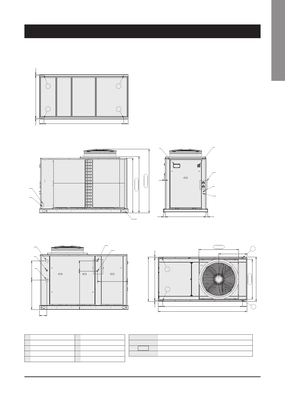
1355
1395
1685
1580
C
D
4 x Ø22
112 1977
112
2323 1054
P2
P1
P3
P4
4 x Ø10
987
1121977
2200
698
987
231054
23
1100
112
1100
P2
P3
P1
P4
763
Front view
Bottom view
Side view Top view
A Water inlet Ø2" gas male F High pressure tap
B Water outlet Ø2" gas male G Low pressure tap
C Electrical auxiliary lines H Gauge kit (accessory)
D Electrical power supply I Main switch
E Hydrometer L Control keypad/display
M Desuperheater water inlet Ø1" gas male (optional)
N Desuperheater water outlet Ø1" gas male (optional)
XXX
Only for HT/HPF fan model
P1, P2, P3, P4 AVM position
Dimensions in mm.
 Loading...