50
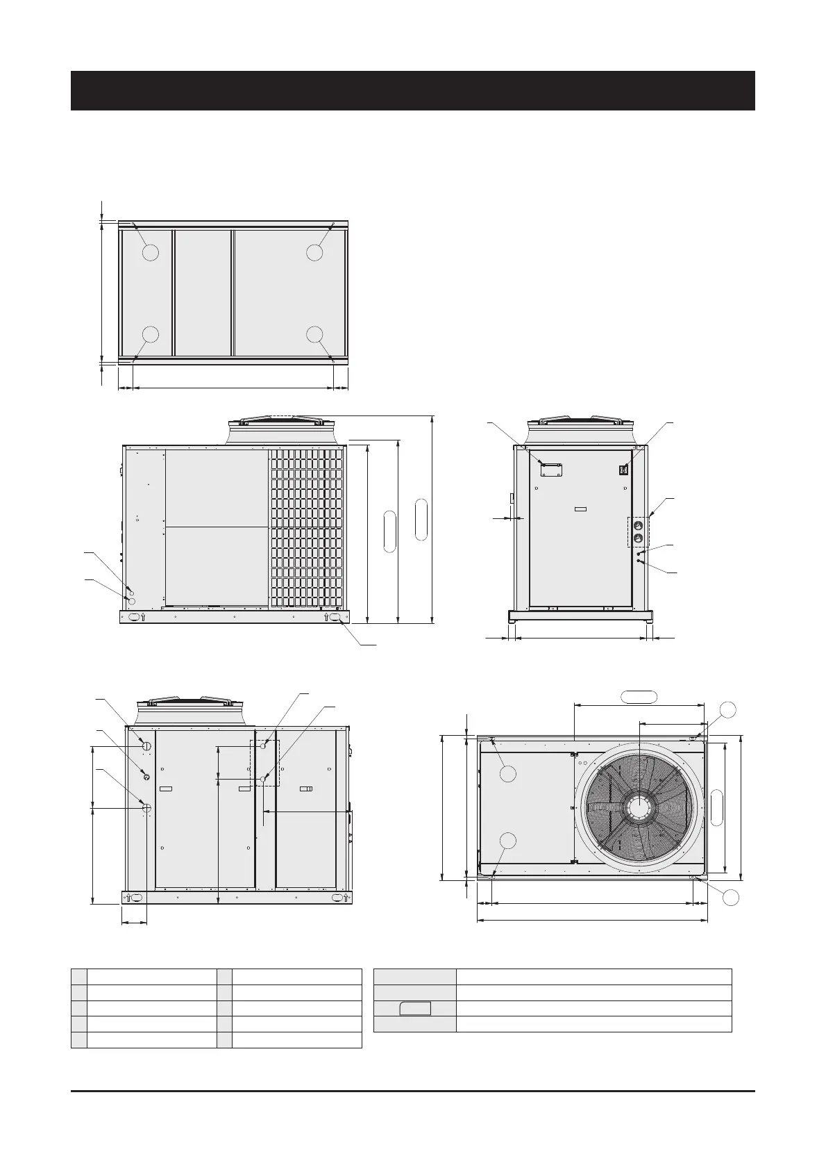
9.5 Dimensional Drawings - Units SyScroll Air CO/HP 40-50
9 - Technical Data
1355
1395
1685
1580
C
D
4 x Ø22
1100
23105423
1750
517
112 1121527
987
987
1100
P2
P1
P3
P4
50 1000 50
25
I
L
H
F
G
250950
470730
188
A
B
E
N
M
23105423
112 1527 112
P3
P4
P2
P1 4 x Ø10
678
Front view
Bottom view
Side view Top view
A Water inlet Ø2” gas male F High pressure tap
B Water outlet Ø2” gas male G Low pressure tap
C Electrical auxiliary lines H Gauge kit (accessory)
D Electrical power supply I Main switch
E Hydrometer L Control keypad/display
M Desuperheater water inlet Ø1” gas male (optional)
N Desuperheater water outlet Ø1” gas male (optional)
XXX
Only for HT/HPF fan model
P1, P2, P3, P4 AVM position
Dimensions in mm.
 Loading...