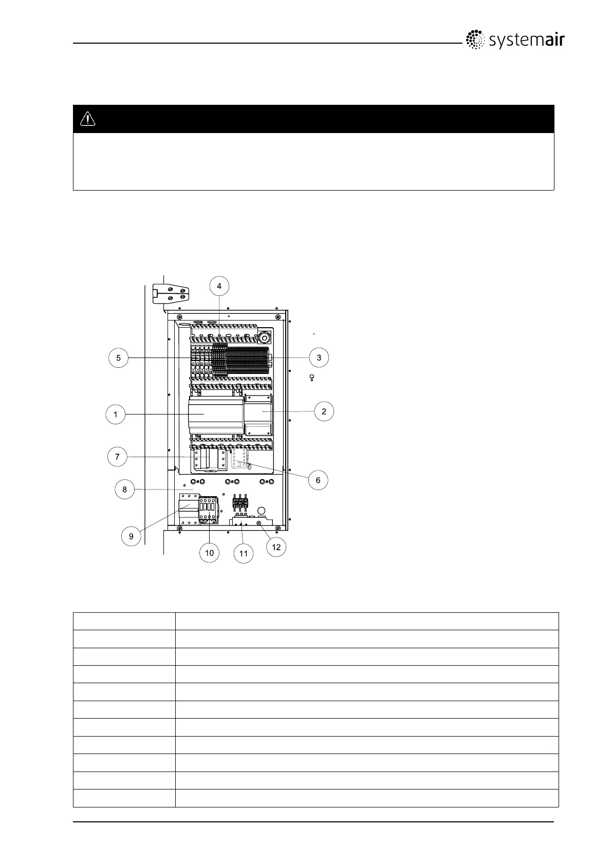
2.4InternalcomponentsElectricalconnectionbox
Danger
•MakesurethattheMainssupplytotheunitisdisconnectedbeforeperforminganymaintenanceor
electricalwork!
•Allelectricalconnectionsmustbecarriedoutbyanauthorizedinstallerandinaccordancewith
localrulesandregulations.
TopvexSR/TR03–06areequippedwithabuiltinregulatorandinternalwiring(gure4).
ThegureshowstheelectricalconnectionboxfortheT opvexTR03–06units.Theconnectionboxforthe
TopvexSR03–06hasthesamelayoutandcomponentswiththedifferencethattheelectricalheateris
situatedinaseparatecompartment.
Fig.4Electriccomponents
PositionDescription
1RegulatorE-28WEB
2
Transformer230/24VAC
3
Terminalsforinternalandexternalcomponents
4
Terminalsforinternalwiring
5
Terminalsformainssupplytotheunit
6
Contactor(K2)On/OffPumpcontrolwater(HWunitsonly,notpresentinEL-units)
7
Automaticfuse
8
Electricheaterframe
9
Automaticfuseforheater
10
Contactor(K3)foron/offcontrolofELheater
TopvexSR/TR03,SR/TR04,SR/TR06OperationandMaintenanceInstructions
206902
6
SystemairAB

 Loading...