_________________________________________________________________________________________________________________
Topvex TR 09, TR12 & TR15 Operation- and maintenance instructions
205000 Systemair AB
3
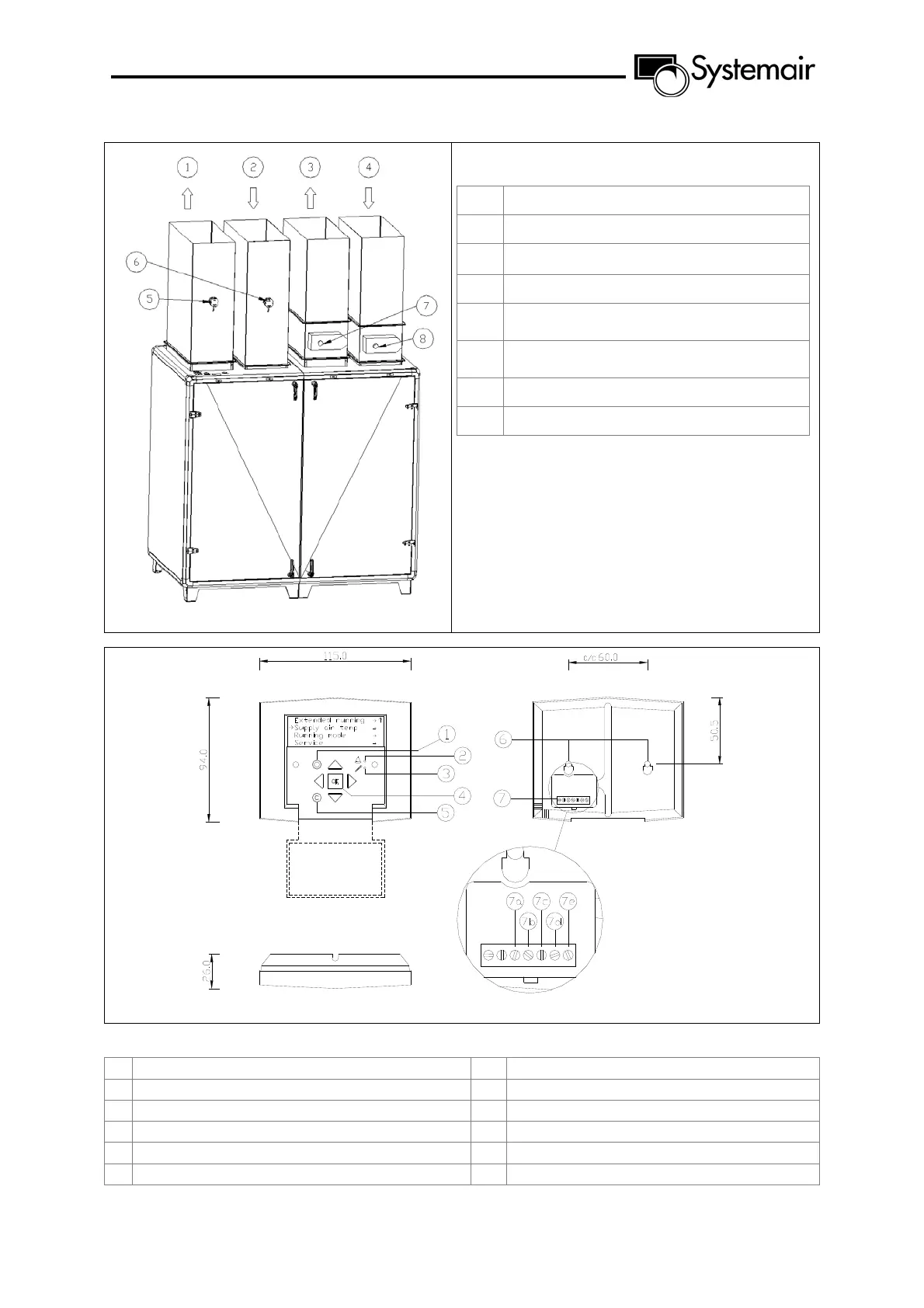
Fig. 4
Description
1.
Alarm button
7.
Connection block
2.
Alarm LED
7a.
Yellow cable
3.
Write enable LED
7b.
Orange cable
4.
OK button
7c.
Red cable
5.
Clearing button
7d.
Brown cable
6.
Mounting holes
7e.
Black cable
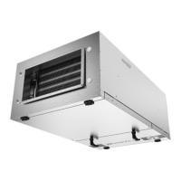
Fig. 3
Description
1.
Supply air
2.
Extract air
3.
Exhaust air
4.
Outside air
5.
VAV pressure transmitter supply air
(accessories)
6.
VAV pressure transmitter extract air
(accessories)
7.
Damper and motor exhaust air (accessories)
8.
Damper and motor outside air (accessories)