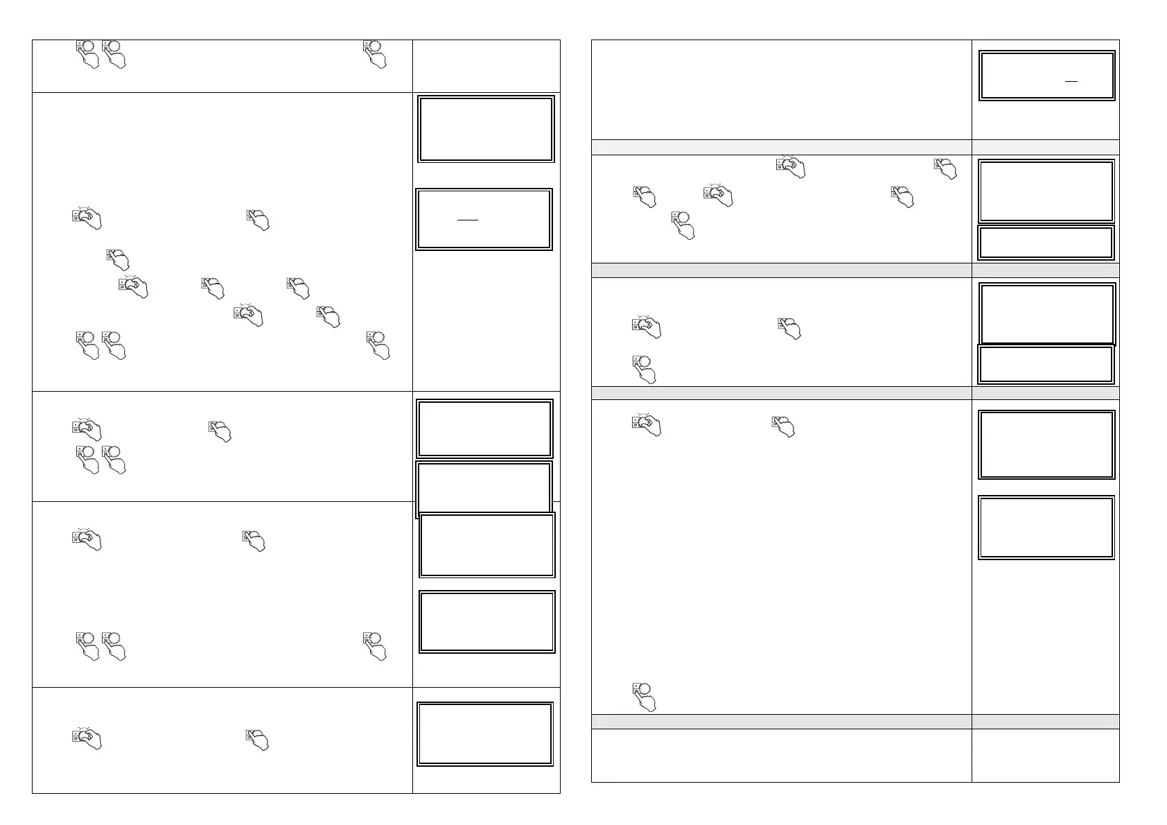
Press (twice) to return to level 1 in the service menu
,
,
once = up one level.
7.11 Configuration DI1-3
The unit is prepared for 7 different digital inputs. DI1-3 can be changed,
but standard function is: When input is closed, the following will happen:
DI1: Both fans = override to high (max) fan speed
DI2: Both fans = override to low (min) fan speed
DI3: Supply fan (SF) = Override to high (max) fan speed, Extract fan (EF)
override to low (min) fan speed
It is possible to change these configurations:
Turn to ” Config DI1-3” . Confirm . The following is
displayed:
Move cursor to position to be changed. Choose between high-
nominal-low-off . Confirm . Continue to change other
positions. Choose wanted fan speeds . Confirm .
Press (twice) for returt to level 1 in the service menu
,
once = up one level.
7.9 DI4-7
Explanation to functions DI4-7 (cannot be configured) can be read.
Turn to ” DI4-7”. Confirm . The following is displayed:
Press (twice) to return to level 1 in the service menu
,
once =
up one level.
7.10 Digital output
Values for the digital outlets can be read:
Turn to ” Digital outlet”. Confirm .
The following is displayed:
SF = Supply fan
EF = Extract fan
Rot. = Rotor motor
S = Sum alarm
Dmp = Damper
Press (twice) to return to level 1 in the service menu
,
once = up one level.
7.11 Factory reset
You can reset all settings and configurations and return to standard
factory settings.
Turn to ”Factory reset” . Confirm .
The following is displayed:
8. Choose language
Standard language is English. Turn to ” Language”. Confirm .
Press and turn to required language. Confirm .
Press "Back" to return to level 1 in service menu.
9. Version (only during service or repair)
If service is required, or when changing PCB, it is important to know the
actual program version in the unit.
Turn to ” Version”. Confirm . The actual version and date is
displayed.
Press to return to level 1 in the service menu.
10. Alarms
You can read status for alarms as follows:
Turn to ”Alarms” . Confirm .
Status for alarms is displayed:
N = No, no alarms Alternatively Y = YES for active alarms
Fan = Fan malfunction. Could be caused by:
- defective fan motor
- blocked fan impeller
- Missing connection between motor and control card (f.ex. loose
connection plug)
NB! If one motor stops due to malfunction, the other fan will also stop
after a few seconds. Alarm will automatically reset when problem is
solved and both fans will start after apx. 15 sec.after the unit is
reconnected to mains supply.
Em t = Disconnected fire thermostat. Reset by pressing red button
inside the unit (see User maual)
Rot = Utilsiktet rotorstans (reimbrudd, defekt motor)
Pb kort = Missing contact between PCU-EC power board, PCU-PB.
Temp = Short circuit or breach in one of the sensor circuits
Filter = Filter time exceeded. See 3, Filter period.
NB! Alarms will reset automatically when problem has been solved.
Only filter alarm must be reset manually, see 3, Filter period.
Press to return to level 1 in the service menu.
11 Return to user menu
Before return to user menu, go back to "1 Password" and lock the system
by changing setting to "Locked" Yes" (se item 1).
Note! In general, all bold texts can only be read - not changed or
adjusted.
Analog output
Digital input
→ Config DI1-3
Config DI1-3
1 SF high EF high
2 SF low EF low
Digital input
Config DI1-3
DI4-7
4 Stop heat 5 Ext.run
6 Filt res
Config DI1-3
DI4-7
Digital output
1: SF 20% 4: S
OFF
2: EF 20% 5: Dmp ON
3: Rot ON
DI4-7
Digital output
Factory reset
Really reset?
NO
Week program
Functions
Language
Functions
Language
Versjon Ver x.x
Language
Version
→ Alarmes
Fan N Pb Fail N
EmT N Temp. N
 Loading...