This document describes the CD Control Panel, an interface for managing Systemair ventilation units. It provides a comprehensive overview of its operation, display symbols, and service menu functions, enabling users to control and maintain their ventilation systems effectively.
Operation and Interface
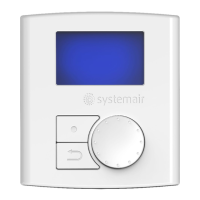
The control panel features a clear display (1) that shows symbols, menus, and settings. A selection knob (2) allows users to navigate through menu lists and adjust settings or values by turning it left or right. A confirm button (3) is used to validate menu choices or settings, while a back button (4) allows users to step back through menu levels.
Display Symbols
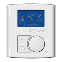
The control panel uses various symbols to indicate the unit's status and allow for adjustments:
- Temperature (Temp): This symbol illustrates the current set temperature. The temperature setting can be adjusted in five steps, from completely empty to a filled symbol, by turning the selection knob. The setting is confirmed with the confirm button.
- Fan Speed (Fan speed): This symbol indicates the current fan speed. The fan speed can be manually set in three steps: Low (A), Nominal (B), and High (C).
- Low ventilation (A): Suitable for periods when the building is unoccupied for an extended time. It can also be set to OFF by activating "Manual fan stop" in the service menu.
- Nominal ventilation (B): Provides the required air change under normal operating conditions.
- High ventilation (C): Used to increase airflow when necessary.
The fan speed is adjusted by turning the selection knob and confirmed with the confirm button.
- Service (Service): This symbol provides access to the service menu by pressing the confirm button.
- Alarm (Alarm): This symbol allows access to the alarm list by pressing the confirm button.
The service menu is structured in three levels, offering extensive control and maintenance options. To enter the service menu, select the service symbol and press the confirm button. The default password for the service level is "1111". If the password is forgotten, "8642" can be used to override it.
Level 1: Service
- Password: Allows users to enter the service level password.
- Change password: Enables setting a new password.
- Filter period: Displays the selected time interval between filter changes and allows resetting the filter period after a change.
- Time/Date: Shows the current date and time and allows for correction.
- Ext/Forc Run (Extended/Forced Run): Programs the unit to operate under specific conditions for an extended time, overriding the week schedule. Users can set the duration in minutes and the fan speed (Low, Nominal, or High).
- Week program: Allows programming the unit's operation according to a weekly schedule, with up to two periods per day. Users can set the week day and time intervals for ON mode.
- Fan speed log: Displays how long the fans have been active at different speed levels (0%, 1-29%, 30-44%, 45-59%, 60-100%). This log can be reset for individual levels, but the right column continues to count.
- Functions: Provides access to advanced settings.
Level 2: Functions
- Heater/Cooler: Configures the unit for heating and/or cooling. Users can set the heater type (None, Electrical, or Water) and cooler type (None or Water).
- Frost protection: Displays and allows adjustment of the frost protection alarm limit for the installed water coil.
- Air flow: Sets individual fan speeds for the Exhaust Fan (EF) and Supply Fan (SF) for each step (Low, Nominal, and High). The maximum difference between EF and SF is 20%.
- Air flow unit: Selects the unit for airflow display (l/s, m³/h, or %).
- Manual fan stop: Determines if it's possible to manually turn off the fans from the control panel. If enabled, fans can be turned off by selecting the empty fan symbol.
- Analog input: Shows analog inputs from active temperature sensors (Supply air, Extract air, Exhaust air, Overheat/Frost protection, Outdoor air).
- Analog output: Displays current analog outputs (0-10V) to hot/cold water actuators and bypass dampers. Users can set these outputs to auto, manual, or off. Manual control allows adjusting the actuator/damper with a 0-10V signal (0V for closed, 10V for opened).
- Digital input: Shows current settings of digital inputs (ON or OFF) for various functions like fan configuration, heater stopped, extended/forced running, damper test, and home/leave modes.
- Config DI 1-3 & DI 4-7: Configures how fans react to digital inputs when switched on or off. This includes setting SF and EF speeds (off, low, nom, high) for different digital input scenarios.
- Digital output: Shows current settings of digital outputs, including SF and EF speeds (as a percentage of maximum speed), rotor motor status (ON/OFF for VR units), alarm status (Y/N), damper status (OFF), and reheater status (Y/N).
- Defrosting: Sets the aggressiveness of the defrosting function (modes 0-5 for VR units, 1-5 for VC units). Users can also allow temporary unbalance of airflow during defrosting (Reduced flow) and view if any defrosting cycle is active.
- Modbus: Provides information about Modbus communication, including address and baud rate.
- Factory reset: Returns the unit to factory settings, erasing all personal configurations.
- Languages: Selects the local language for the interface.
- Versions: Displays the current software version and unit information.
- Alarms: Shows a list of triggered alarms (indicated by Y).
Usage Features
Setting Temperature:
The supply air temperature is manually set in five steps via the main menu display using the temperature symbol.
- With an electrical or water re-heater installed, temperature steps are 12.0, 14.5, 17.0, 19.5, and 22.0 °C (default 12.0 °C).
- Without a re-heater or if it's deactivated, temperature steps are 15.0, 16.0, 17.0, 18.0, or 19.0 °C (default 15.0 °C).
Each step is visually represented by an increasing fill of the temperature symbol.
Manual Setting of Fan Speed:
Users can manually adjust the fan speed in the main menu display by selecting the fan symbol and confirming. This allows overriding the programmed week schedule until the end of the current time period. Fan speed can also be set to OFF by activating "Manual fan stop" in the service menu.
Manual Summer Mode:
Manual summer mode is activated when a temperature lower than 12 °C is selected, causing the temperature symbol to appear empty.
- For VC units, the bypass damper opens (10V control signal).
- For VR units, the rotor stops.
- If a re-heater is active, it switches off during manual summer mode.
This mode automatically aborts after two minutes if the supply air temperature drops to ≤ 5 °C. If a water heater battery is installed and activated, manual summer mode is aborted if the outdoor air or supply air temperature is ≤ 5 °C.
Cool Recovery:
Cool recovery occurs when there is a cooling need and the outdoor air temperature is higher than the extract air temperature.
Software Configuration for Electrical Heater:
To configure an electrical heater:
- Go to the service menu using the selection knob.
- Enter the service level password (default "1111").
- Navigate to "Functions".
- Choose "Heater/Cooler".
- Select "Heater: Electrical".
The unit is then ready to operate with the installed electrical heater.
Maintenance Features
The service menu provides several features to assist with maintenance:
- Filter period: Allows tracking and resetting the filter change interval, ensuring timely filter replacement.
- Fan speed log: Provides detailed information on fan operation hours at different speeds, which can be useful for predictive maintenance and troubleshooting.
- Frost protection: Allows monitoring and adjusting the alarm limit for frost protection, helping to prevent damage to the water coil.
- Alarms: Displays a list of triggered alarms, enabling quick identification and resolution of issues.
- Factory reset: Offers an option to revert all settings to their original factory state, which can be useful for troubleshooting or preparing the unit for a new installation.