11
GB
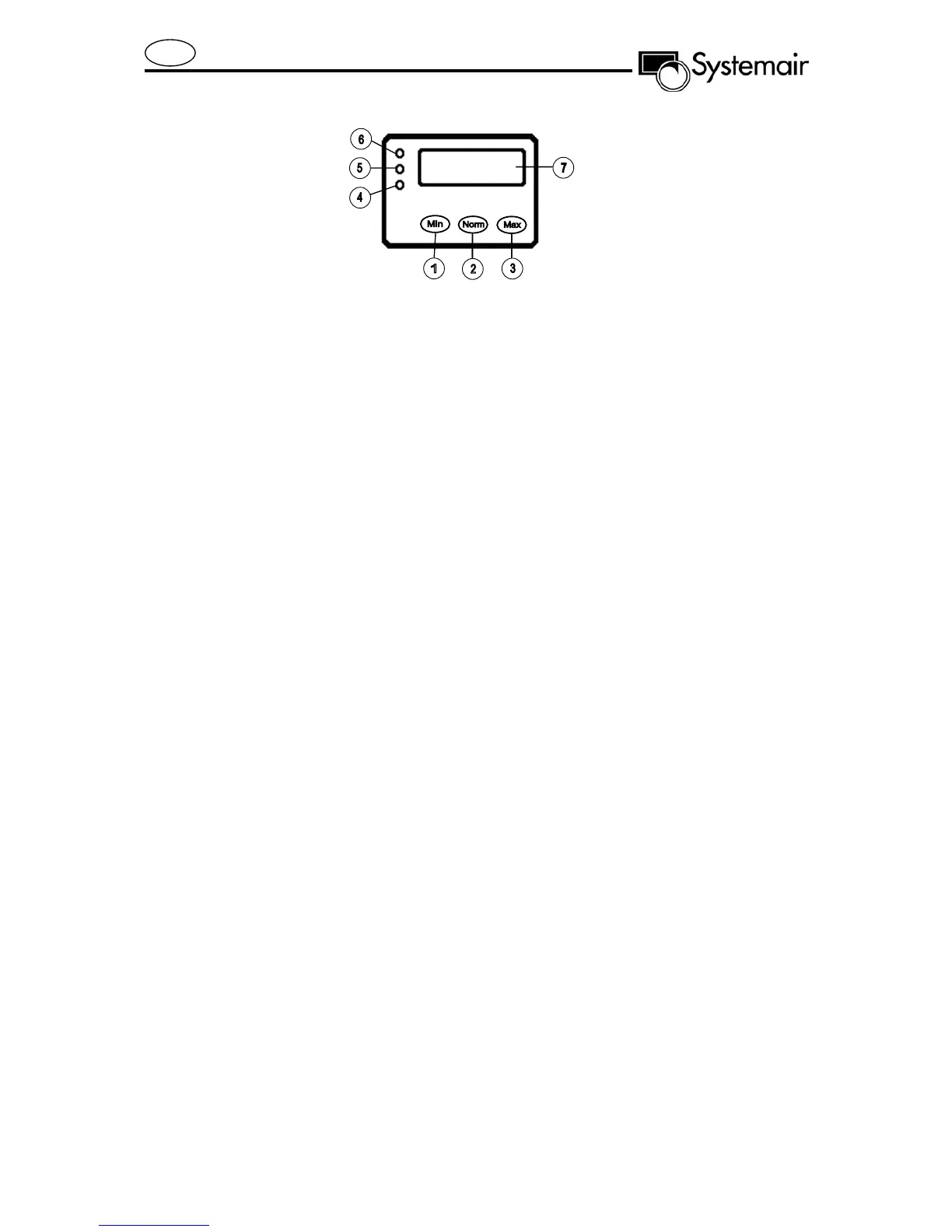
Fig. 2
OPERATION (Fig. 2)
The unit is controlled from a built-in or separate controller, with the following
functions:
Switch for airflow. Fan speed can be controlled in 3 steps by pressing buttons marked min.,
norm. or max.
Airflow (fan speed)
MIN. (1) Minimum ventilation. To be used when the building is not in use.
NORM. (2) Normal ventilation. Set during commissioning of the system to supply required
airflow to the building
MAX. (3) Forced ventilation. Is used when extra airflow is required.
Lamp signal (green, yellow or red)
When starting the unit, all 3 lamps will light and the unit will test contact with motors and
temperature sensors.
Green (4) Operation signal.
The unit is in operation.
Yellow (5) Flashing light, and "Filter" is displayed (7):
The set operation period between filter changes has expired. The efficiency will
be reduced until new filters have been installed.
Yellow (5) Fixed light signal, and "Defrost" is displayed (7):
Defrosting proceeding. Automatic reset to normal operation when defrosting
period is finished.
Red (6) Flashing light, and "Motor error" is displayed (7):
Malfunction on motor(s)/sensors.
OPERATION (Fig. 2)
Display (7)
During normal operation (NORM) the display shows airflows in l/s (Q).
During minimum operation (MIN) the display shows "Reduced Flow".
During forced operation (MAX) the display shows "Maximum flow".
If malfunction occurs, the failure will be displayed. This message will override the operation signal in
the display.
The system should operate continuously, and only be stopped for maintenance and
service.